
Fault-tolerance pattern and switching protocol for multiple hot and cold standby redundancies

a technology of fault tolerance and switching protocol, applied in the field of fault tolerance control system, can solve the problems of high system resource consumption, pattern not scaling well, and inconvenient scaling of dual-duplex pattern to handle more than one failure, so as to reduce the processing load of controllers, and reduce the overall processing burden of one more controller

Active Publication Date: 2017-09-28
GM GLOBAL TECH OPERATIONS LLC
View PDF8 Cites 27 Cited by
  • Summary
  • Abstract
  • Description
  • Claims
  • Application Information

AI Technical Summary

Benefits of technology

The invention described in this text reduces the workload for controllers by designating one controller as the primary and another as the hot standby. This means that in case of failure, the hot standby controller can takeover immediately without needing to switch from cold standby mode. As a result, the backup controller can always be ready to take over in case of failure. This helps to reduce the processing burden on controllers and frees up resources.

Problems solved by technology

Scaling a dual-duplex pattern towards handling more than one failure may not be cost effective approach given that more than one controller_failure may need to be tolerated in a same driving cycle.
As a result, if a dual-duplex design is utilized and two controller_failures must be tolerated, then three controllers must be utilized and a same function will be executed simultaneously and independently six times which results in costly and inefficient consumption of system resources.
For a triple modular redundancy approach, all controllers execute the same function, but this pattern does not scale well.

Method used


Image

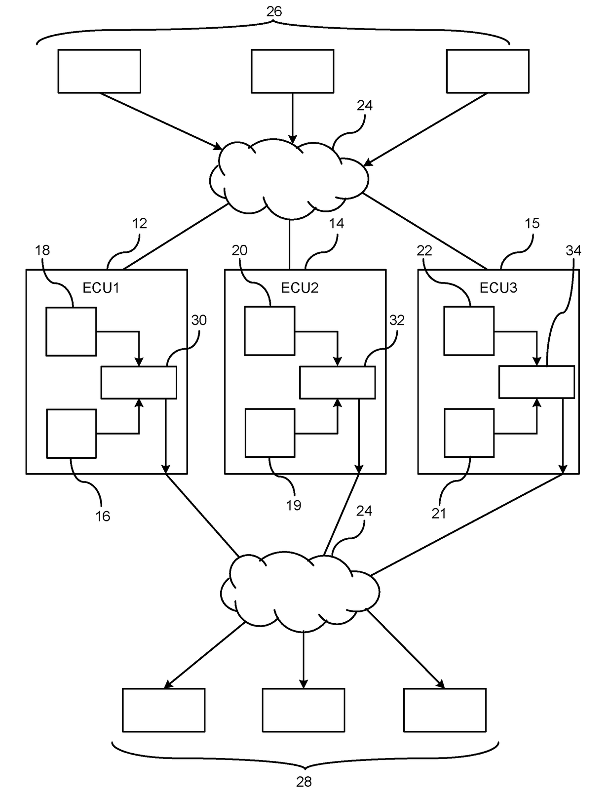
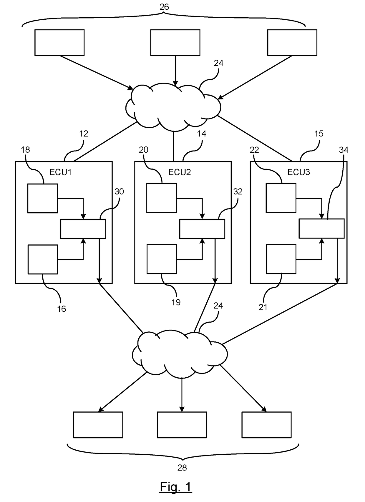
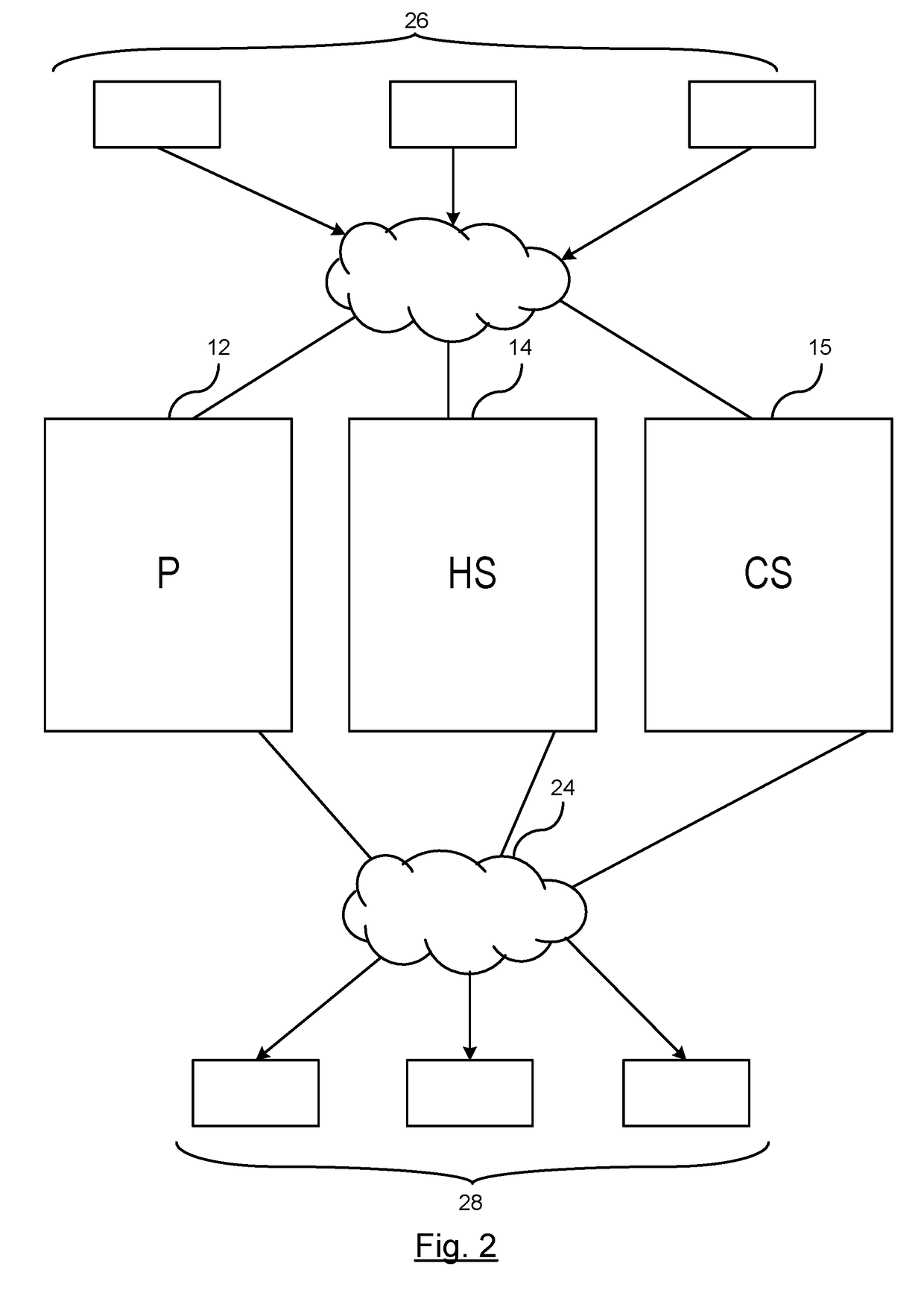
  • Fault-tolerance pattern and switching protocol for multiple hot and cold standby redundancies
  • Fault-tolerance pattern and switching protocol for multiple hot and cold standby redundancies
  • Fault-tolerance pattern and switching protocol for multiple hot and cold standby redundancies

Examples


Embodiment Construction

[0017]The following detailed description is meant to be illustrative in understanding the subject matter of the embodiments and is not intended to limit the embodiments of the subject matter or the application and the uses of such embodiments. Any use of the word “exemplary” is intended to be interpreted as “serving as an example, instance, or illustration.” Implementations set forth herein are exemplary are not meant to be construed as preferred or advantageous over other implementations. The descriptions herein are not meant to be bound by any expressed or implied theory presented in the preceding background, detailed description or descriptions, brief summary or the following detailed description.

[0018]Techniques and technologies may be described herein in terms of functional and / or logical block components, and with reference to symbolic representations of operations, processing tasks, and functions that may be performed by various computing components or devices. Such operation...


PUM


Abstract

A method for fault tolerant controller readiness. Executing functions by a first controller operating in a primary status mode. Operating in a hot standby status mode by a second controller and mirroring the first controller by executing functions to operate as a redundant controller. Operating in a cold standby status mode by at least one backup controller under normal operating conditions. The second controller is reconfigured while operating under normal operating conditions from the hot standby status mode to the primary standby status mode if a failure occurs in the first controller. Reconfiguring the at least one backup controller operating under normal operating conditions from cold standby status mode to hot standby status mode to operate as a redundant controller in response to the reconfiguring the second controller from the hot standby status mode to the primary status mode.

Description

BACKGROUND OF INVENTION[0001]An embodiment relates to fault tolerant control systems.[0002]Systems which provide safety functions typically utilize redundant controllers to ensure safety by shutting down functions that have experienced a fault or failure. If a fault is detected, the controller is shut down or the controller fail silent where no signals are generated by the controller and a secondary controller is reconfigured to become the primary controller.[0003]Some systems try to implement control systems utilizing a fail-operational system where additional controllers are used to ensure that a safe operation can be continued for a duration of time, such as dual duplex controllers or a triple modular redundancy approach. In a dual-duplex approach, if a first controller fails and fails silent, a second controller will be activated and all actuators will switch over to rely on requests from the second controller. Unlike software faults where a fault in one controller would be pres...

Claims


Application Information

Patent Timeline
IPC IPC(8): G06F11/20G06F11/16
CPCG06F11/2033G06F2201/805G06F11/2097G06F11/1658B60R16/0231G05B9/03G06F11/1641G06F11/2028G06F11/2041G06F11/2048
Inventor SAMII, SOHEILFUHRMAN, THOMAS E.OSELLA, MASSIMO
Owner GM GLOBAL TECH OPERATIONS LLC
Learn More