Radiation detector and radiography apparatus having the same

a radiography apparatus and detector technology, applied in the direction of instruments, patient positioning for diagnostics, radiation generation arrangements, etc., can solve the problems of large amount of heat generated in elements, non-uniform image, noise generated, etc., to reduce noise from ground loops, reduce noise, and stabilize radiation image

Active Publication Date: 2017-10-05
DRTECH
View PDF5 Cites 2 Cited by
  • Summary
  • Abstract
  • Description
  • Claims
  • Application Information

AI Technical Summary

Benefits of technology

[0021]A radiation detector according to an embodiment of the present invention may minimize ground loop noise by electrically connecting a ground line in a printed circuit board to an intermediate plate in a uniform manner, and emit sufficient radiation on an automatic exposure control sensor by using the intermediate plate capable of transmitting radiation. Therefore, the stable radiation image may be obtained, and a patient who is the object receiving radiation may be protected from an excessive radiation dose through automatic exposure control of the radiation.
[0022]A radiation detector according to an embodiment of the present invention may obtain a stable radiation image by providing an intermediate plate, on which a metal layer is formed on the opposite surface (hereinafter referred to as the back surface) to the surface on which radiation is emitted on a base plate, to form a shield for a ground potential connected to a ground line of a printed circuit board, and thereby shield outside noise. Moreover, by electrically connecting the metal layer formed on the back surface of the intermediate plate that is formed as the shield for the ground potential to the ground line of the printed circuit board, the separation distance may be minimized to minimize ground loop noise. When the ground loop noise is minimized, an even more stable radiation image may be obtained.
[0023]In addition, in a radiation detector according to an embodiment of the present invention, a metal layer on the back surface of a base plate included in an intermediate plate may be coupled to a frame of a housing such that heat generated in a printed circuit board is effectively released to the outside through conduction. Thus, since the radiation detector according to the present invention is able to shield the heat conducted to a radiation detection panel, image noise that is caused by heat may be removed. Therefore, the radiation detector according to the present invention may obtain an even more stable and sharp radiation image.
[0024]Consequently, a radiation detector according to an embodiment of the present invention may be designed as a small, film-type digital radiography (DR) mammography cassette capable of maintaining high robustness and noise tolerance.

Problems solved by technology

This becomes a source of the noise generated in an image.
Meanwhile, when the radiography apparatus is operated, a large amount of heat is generated in elements, in particular, the read out integrated circuit, mounted on a printed circuit board.
Accordingly, since the dark current in a photoelectric conversion element and leakage current in a thin film transistor (TFT) increase, and the amount of fixed noise changes, there is a problem of being a cause of non-uniformity in the image.

Method used


Image

  • Radiation detector and radiography apparatus having the same
  • Radiation detector and radiography apparatus having the same
  • Radiation detector and radiography apparatus having the same

Examples


Embodiment Construction

[0035]Hereinafter, specific embodiments will be described in detail with reference to the accompanying drawings. The present invention may, however, be embodied in different forms and should not be construed as limited to the embodiments set forth herein. Rather, these embodiments are provided so that this disclosure will be thorough and complete, and will fully convey the scope of the present invention to those skilled in the art. In the figures, the dimensions of layers and regions are exaggerated for clarity of illustration. Like reference numerals refer to like elements throughout.

[0036]Hereinafter, exemplary embodiments of the present invention are described with reference to the accompanying drawings.

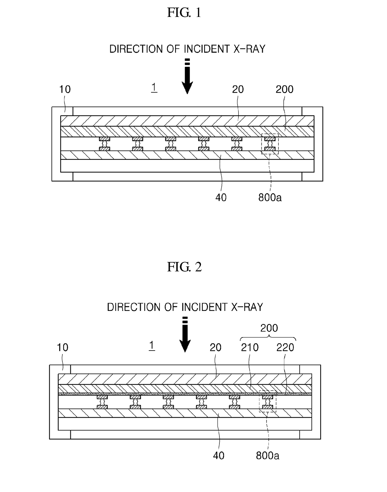
[0037]FIG. 1 is a cross-sectional view of a radiation detector 1 according to an embodiment of the present invention. Referring to FIG. 1, the radiation detector 1 according to an embodiment of the present invention may include a housing 1, a radiation detection panel 20, an inter...


PUM


Abstract

The present invention proposes a radiation detector including a housing, a radiation detection panel accommodated in the housing and converting radiation incident from the outside of the housing into an electric signal, a printed circuit board electrically connected to the radiation detection panel and an intermediate plate that is disposed between the radiation detection panel and the printed circuit board, supports the radiation detection panel, and is electrically connected to the ground line of the printed circuit board, wherein the intermediate plate is transmissive to the radiation.

Description

TECHNICAL FIELD[0001]The present invention relates to a radiation detector detecting radiation, and a radiography apparatus having the same.BACKGROUND ART[0002]A radiography apparatus is an apparatus capable of obtaining internal images of an object by using the radiation that was emitted to the object and passed through the object. Since radiation transmissivity differs according to the properties of the materials constituting the object, the intensity of the radiation that passes through the object may be detected to thereby image the internal structure of the object.[0003]Here, due to the influence of noise that is generated from a light-receiving element or a read out integrated circuit (read out IC), and the like, which are included in the radiography apparatus, each sensor cell in a radiation detection panel may output a radiation having a different intensity, even when radiation having the same intensity is incident on the radiation detector in the radiography apparatus. This...

Claims


Application Information

Patent Timeline
Patent Type & Authority Applications(United States)
IPC IPC(8): A61B6/00A61B6/04A61B5/00G03B42/02
CPCA61B6/4283A61B6/502A61B5/0091A61B6/4258A61B6/5258A61B6/40A61B6/542A61B6/545A61B6/0414G01T1/161G03B42/02A61B6/4233G01T7/00A61B6/00
Inventor HAN, SEUNG ZOOCHOI, JIN HYUNSHIN, CHOUL WOOKIM, JUNG SEOKOH, YOUNG JONGLEE, JAE DONG
Owner DRTECH
Why Eureka
Try Eureka