Gas turbine engine dual sealing cylindrical variable bleed valve

a technology of variable bleed valve and gas turbine engine, which is applied in the direction of machines/engines, mechanical equipment, transportation and packaging, etc., can solve the problem of increasing the difficulty of bleeding enough air

Active Publication Date: 2017-10-05
GENERAL ELECTRIC CO
View PDF5 Cites 14 Cited by
  • Summary
  • Abstract
  • Description
  • Claims
  • Application Information

AI Technical Summary

Benefits of technology

[0015]An annular fan frame rotatably supports the fan and an annular fan hub frame supports an engine nacelle inwardly bounding the bypass flow path. A power gear box may be operably disposed between the low pressure turbine and the fan for adjusting rotational speed of the fan relative to the low pressure turbine.

Problems solved by technology

This increases the difficulty of bleeding sufficient amounts of air from downstream of the booster to the fan bypass duct for protecting boosters from stall.

Method used


Image

  • Gas turbine engine dual sealing cylindrical variable bleed valve
  • Gas turbine engine dual sealing cylindrical variable bleed valve
  • Gas turbine engine dual sealing cylindrical variable bleed valve

Examples


Embodiment Construction

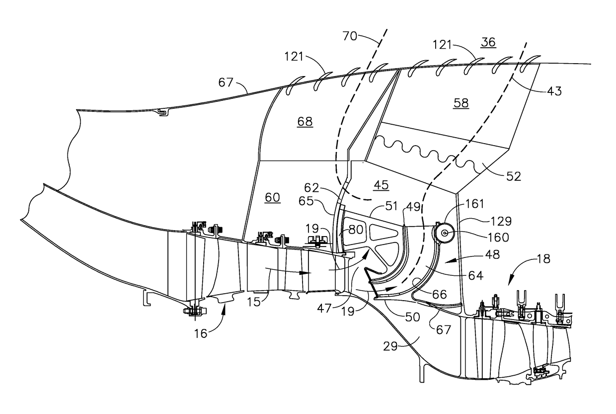
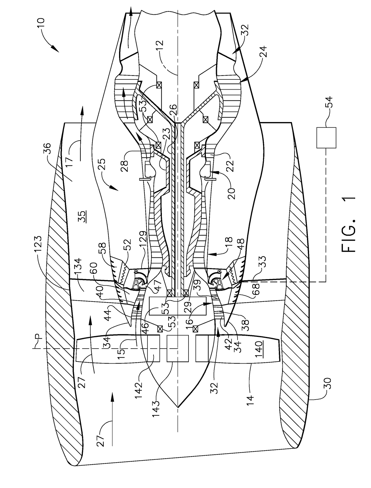
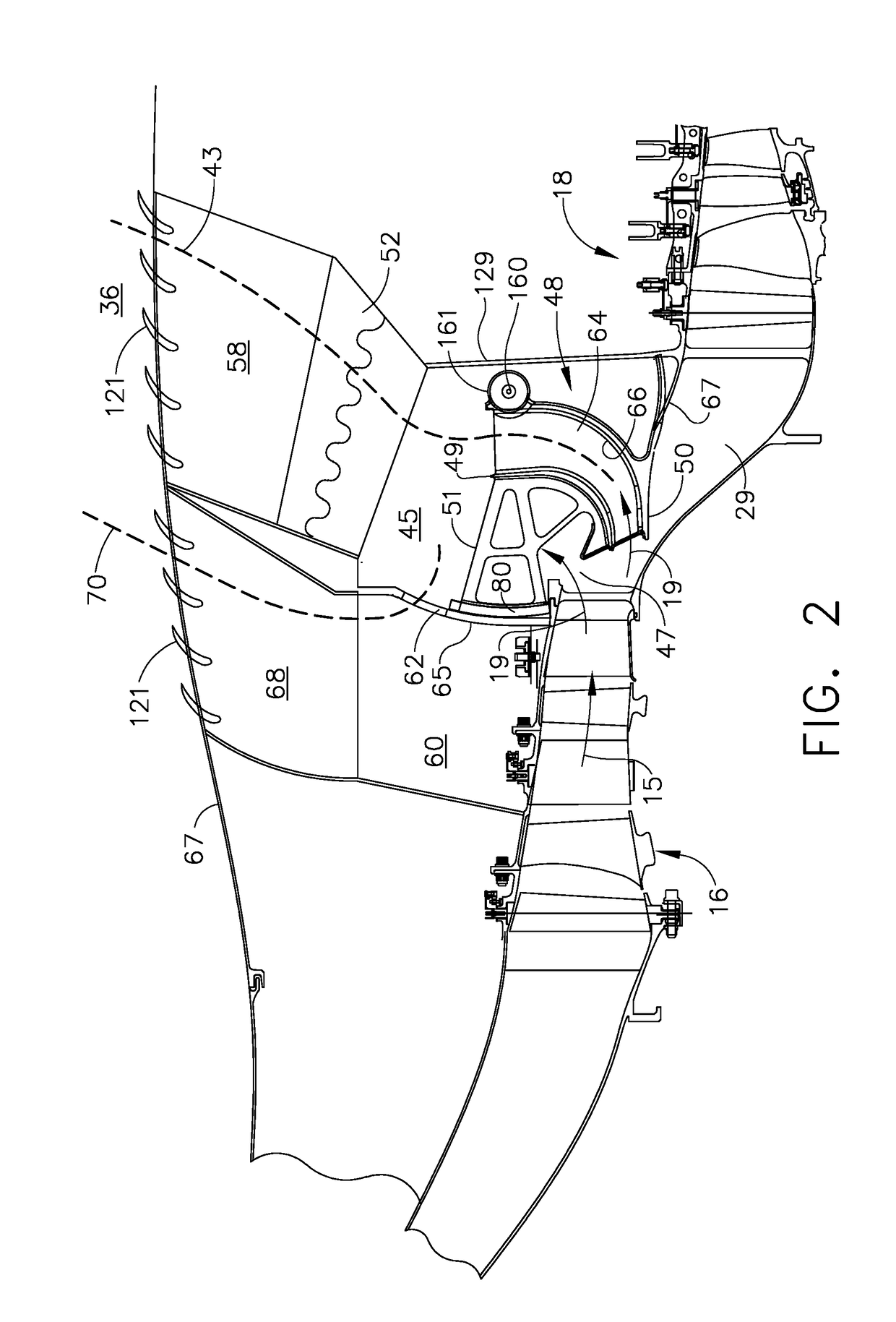
[0028]Illustrated in FIG. 1 is an exemplary aircraft turbofan gas turbine engine 10 circumscribed about an engine centerline axis 12 and suitably designed to be mounted to a wing or fuselage of an aircraft. The engine 10 includes, in downstream serial flow communication, a fan 14, a low pressure compressor or booster 16, a high pressure compressor 18, a combustor 20, a high pressure turbine (HPT) 22, and a low pressure turbine (LPT) 24. A core engine 25 includes the HPT or high pressure turbine 22 drivingly connected by a high pressure drive shaft 23 to the high pressure compressor 18 and the combustor 20. The LPT or low pressure turbine 24 is drivingly connected by a low pressure drive shaft 26 to both the fan 14 and the booster 16.

[0029]The fan 14 may be rotatable about the engine centerline axis 12 by the low pressure drive shaft 26 across a power gear box 46 as illustrated in FIG. 1. The power gear box 46 includes a plurality of gears for adjusting the rotational speed of the fa...


PUM


Abstract

Axially adjacent annular booster bleed aft and forward plenums with annular common wall therebetween extend radially outwardly from transition duct. Variable bleed valve includes bleed valve door in bleed inlet in transition duct, attached to rotatable valve body rotatable about axis of rotation, operable to open and close bleed inlet to aft plenum. Rotatable plenum door clocked or circumferentially spaced apart from variable bleed valve door and attached to rotatable valve body, operable to close and open up and control flow through an inter plenum aperture in common wall. Aft and forward bleed exhaust ducts extend from booster bleed aft and forward plenums to bypass flow path. One or more heat exchanger, such as from thermal management system, may be disposed in the bleed exhaust ducts. Heat exchangers may be used for cooling oil for power gear box and/or engine bearings, air conditioning, or variable frequency generator.

Description

BACKGROUND OF THE INVENTIONField of the Invention[0001]The invention relates to gas turbine engine variable bleed valves between a booster and a core engine compressor and, more particularly, to such valves used to prevent surge and help provide thermal management.Description of Related Art[0002]It is well known in the gas turbine engine field to provide variable bleed valves (VBVs) around the engine, typically, doors that open to provide a bleed flowpath to bleed off compressed air between the booster and core engine compressor of gas turbine engines. The air is often bled from what is referred to as a goose neck flowpath between the booster and core engine compressor. Aircraft fan jet gas turbine engines and marine and industrial derivatives of such engines have employed various forms of curved flow paths and VBV bleed doors that are retracted into the flowpath casing so as to form an entrance to a bleed duct that bleeds booster or low pressure compressor discharge airflow to avoi...

Claims


Application Information

Patent Timeline
Patent Type & Authority Applications(United States)
IPC IPC(8): F02C9/18B64D13/08F01D25/14F02C7/18F02C3/04F02K3/06
CPCF02C9/18F02C3/04F02K3/06F01D25/14F05D2270/112B64D13/08F05D2220/323F05D2260/213F02C7/18F02C7/185F01D17/105F02K3/075F05D2250/411F05D2270/101F04D27/023F04D27/0215
Inventor JOHNSON, STEVEN DOUGLASMILLER, BRANDON WAYNEGONYOU, CRAIG ALAN
Owner GENERAL ELECTRIC CO
Why Eureka
Try Eureka