
Throttle unit and a static pressure bearing device equipped with the throttle unit, and a method of manufacturing a grooved block

a technology of static pressure bearing and throttle unit, which is applied in the direction of manufacturing tools, mechanical equipment, rotary machine parts, etc., can solve the problems of difficult cleaning of the unit, high cost of preparing such a needle, and the strength of the restriction may change, so as to reduce the weight of parts, and improve the quality of parts.

Inactive Publication Date: 2017-10-05
FANUC LTD
View PDF15 Cites 4 Cited by
  • Summary
  • Abstract
  • Description
  • Claims
  • Application Information

AI Technical Summary

Benefits of technology

The present invention provides a throttle unit and a static pressure bearing device equipped with the throttle unit, and a method of manufacturing a grooved block. The invention allows for accurate groove machining and obtains an accurate groove shape by measuring the groove depth and width using a microscope. The throttle unit reduces the weight of parts, has a compact structure, decreases manufacturing steps and costs, is highly reliable, and easy to disassemble and clean.

Problems solved by technology

Problems of the needle throttle unit include the following points: the man hours for assembling the unit are large since the structure for incorporating the needle is complicated; the individual differences in the restriction strength are large since the variety of inner diameter errors of the respective needles is likely to affect the restriction strength; the unit has low reliability since the needle tends to fall off, and thus the restriction strength may change over time; due to a limit to the needle thinness, a thin needle is required to be long and have a special shape, for securing a certain degree or more of the restriction strength, so that the cost is high for preparing such a needle; and it is difficult to clean the unit when the needle is clogged with foreign material or the like.
Problems of the screw throttle unit include the following points: The number of parts or components is large and the structure of the unit is complicated, so that man hours for assembling are large; Precise adjustment is indispensable and the individual differences in the restriction strength become large depending on the adjustment state; The restriction strength may change in time due to looseness of the screw; The cost is high because of the large number of components; And it is difficult to clean the unit when the unit is clogged with foreign material or the like.

Method used


Image

  • Throttle unit and a static pressure bearing device equipped with the throttle unit, and a method of manufacturing a grooved block
  • Throttle unit and a static pressure bearing device equipped with the throttle unit, and a method of manufacturing a grooved block
  • Throttle unit and a static pressure bearing device equipped with the throttle unit, and a method of manufacturing a grooved block

Examples


Embodiment Construction

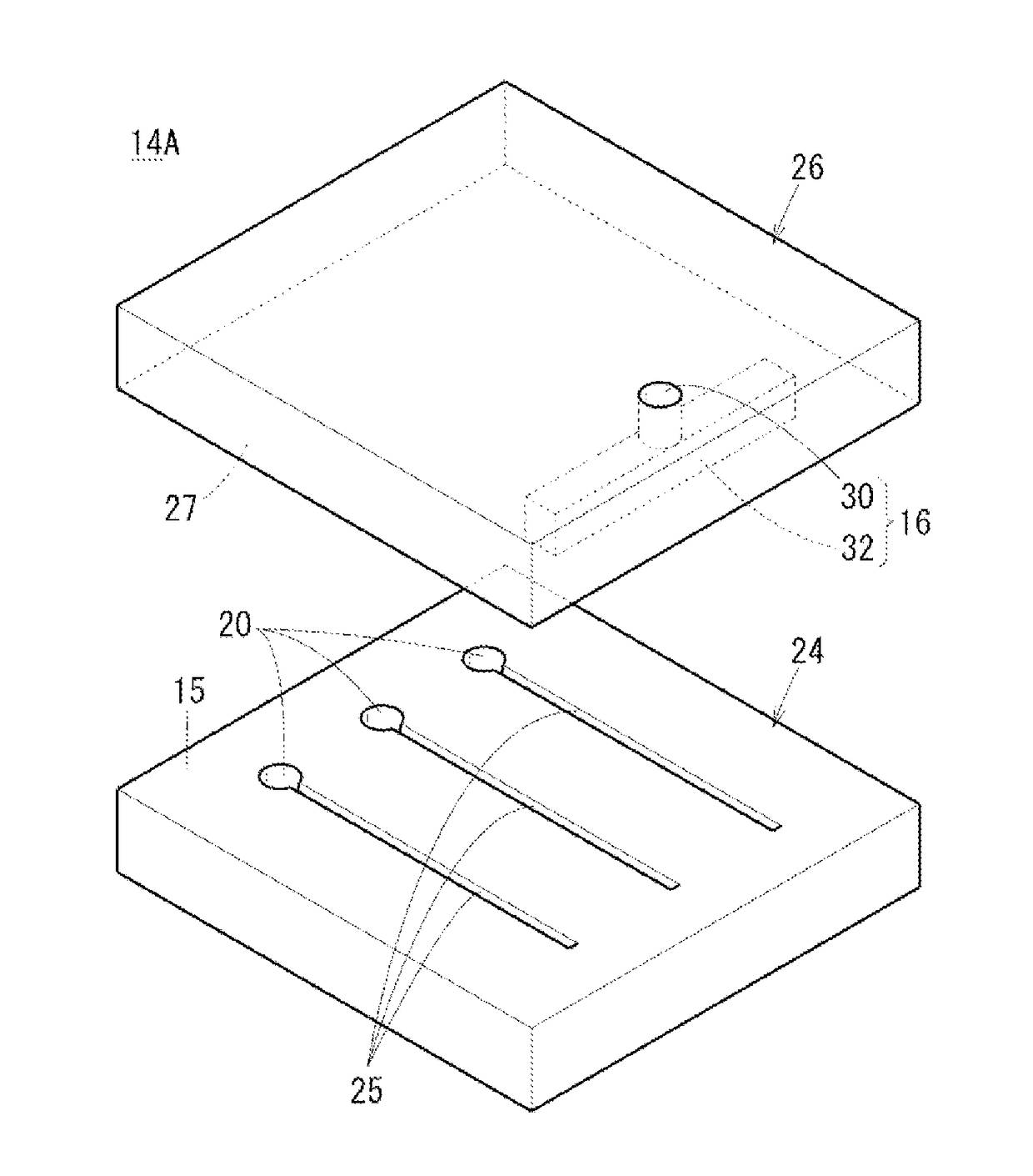
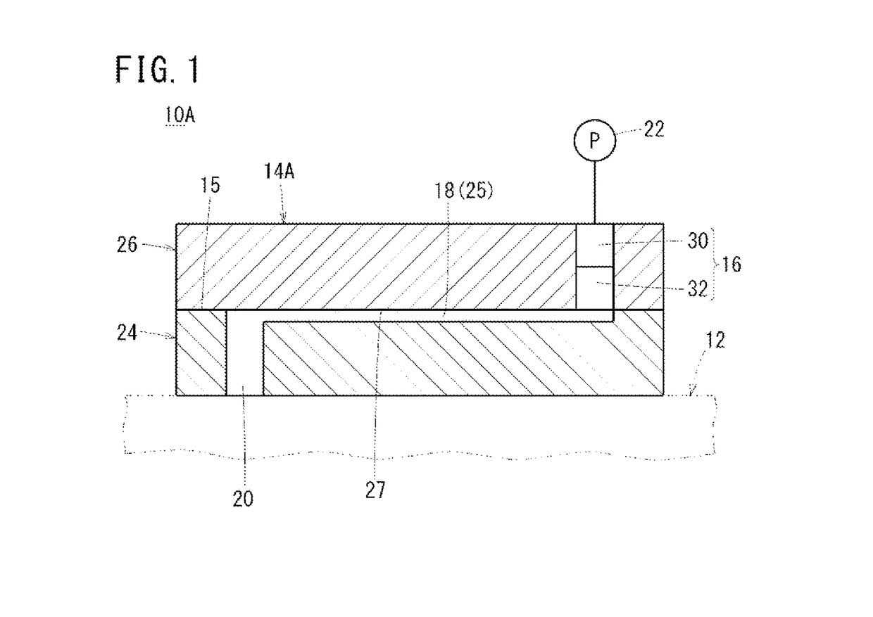
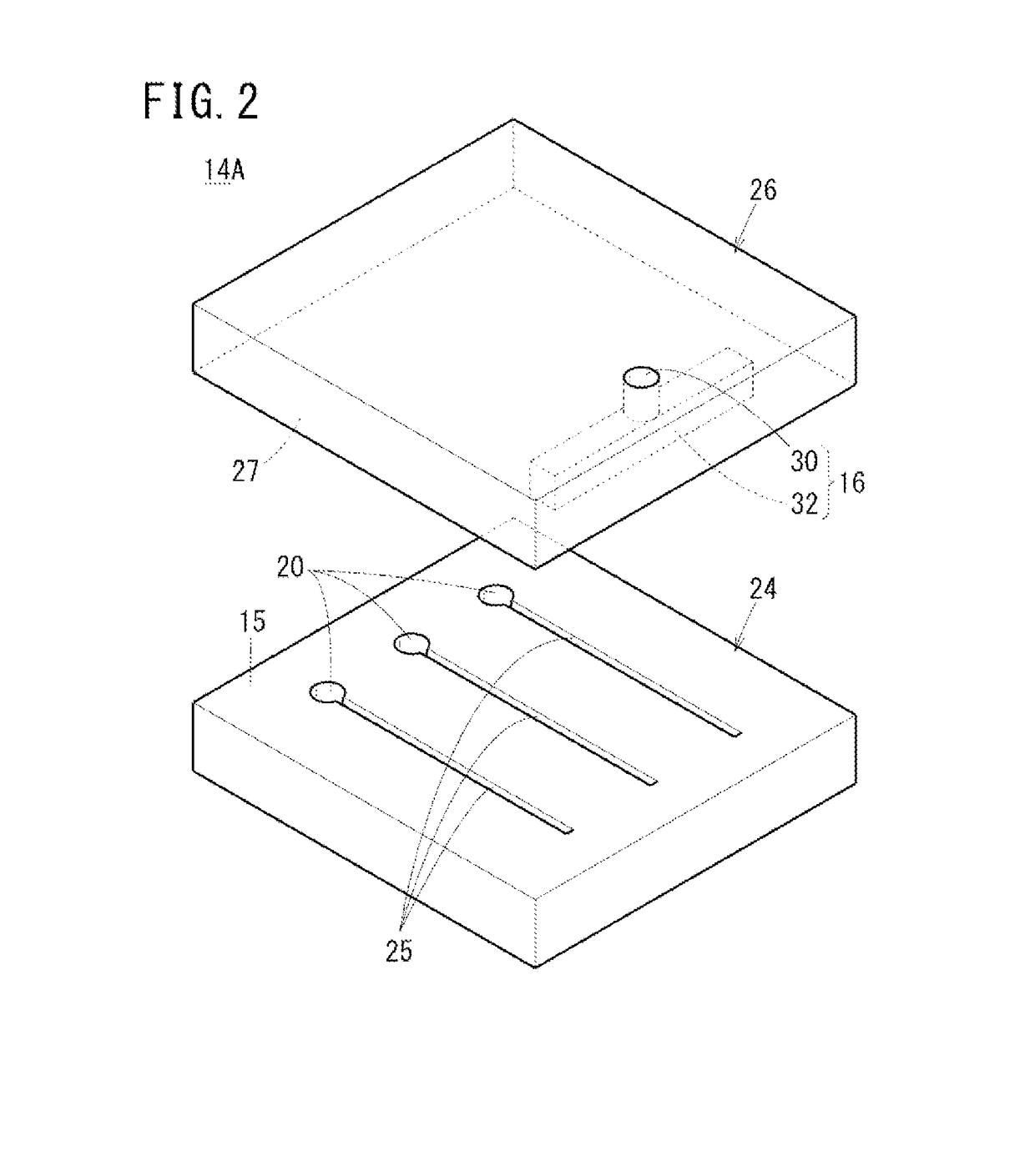
[0057]A preferred embodiment of a throttle unit and a static pressure bearing device having the throttle unit, and a method of manufacturing a grooved block according to the present invention will be described below with reference to the accompanying drawings.

[0058]A static pressure bearing device 10A shown in FIG. 1 is equipped with a bearing unit 12, and a throttle unit 14A attached to the bearing unit 12. Though the detailed structure is not shown, the bearing unit 12 is equipped with a structure with a linear motion axis, in which a guide as a fixed portion and a slide as a movable portion are provided. A plurality of static pressure pockets are formed on a bearing surface of the slide or the guide. When a working fluid such as air is supplied to the static pressure pockets, the slide floats above the guide by the static pressure of the working fluid and can move along the guide in a non-contact manner. The bearing unit 12 may have a structure with a rotary axis.

[0059]The thrott...


PUM

PropertyMeasurementUnit
Depthaaaaaaaaaa
Widthaaaaaaaaaa

Abstract

A throttle unit is equipped with a grooved block including at least one minute groove formed on a plane surface, and an opposite block having a plane surface which is opposite to the minute groove. The grooved block and the opposite block are detachably joined so as to be opposite to each other. A throttle fluid path is formed by the minute groove and the plane surface of the opposite block. At least one surface of each of the minute groove is constituted by a curved surface or an inclined surface that is inclined with respect to the plane surface of the grooved block.

Description

CROSS-REFERENCE TO RELATED APPLICATION[0001]This application is based upon and claims the benefit of priority from Japanese Patent Application No. 2016-076039 filed on Apr. 5, 2016, the contents of which are incorporated herein by reference.BACKGROUND OF THE INVENTION[0002]Field of the Invention:[0003]The present invention relates to a throttle unit and a static pressure bearing device equipped with the throttle unit, and a method of manufacturing a grooved block.[0004]Description of the Related Art:[0005]In machine tools, as a guide device for a table having a linear motion axis or a rotational axis, static pressure bearings are used. In a static pressure bearing, in a case of a structure with a linear motion axis, for example, a static pressure pocket is formed on a bearing surface of a slide or a guide, and a working fluid such as oil or air is supplied to the static pressure pocket. The slide floats above the guide as a fixed portion by the static pressure of the working fluid, ...

Claims


Application Information

Patent Timeline
IPC IPC(8): F16C32/06F16C29/02
CPCF16C32/0622F16C29/025F16C2322/39F16C2220/60F16C32/0655F16C32/0681F16C32/0625F16C32/0659F16C2240/42F16L55/027F16C32/0614B23Q1/38
Inventor SUZUKI, TOYOAKIMUROTA, MASAHIRO
Owner FANUC LTD
Learn More