Optical lens assembly, image capturing apparatus and electronic device

a technology of optical lens applied in the field of optical lens assembly and image capturing apparatus, can solve the problems of inability to reduce the size of the product equipped with the conventional lens assembly with inability to inability to concomitantly meet the requirements of a wide field of view, etc., to achieve the effect of effectively correcting the field curvature, reducing the angle, and smooth formation

Active Publication Date: 2017-10-12
LARGAN PRECISION
View PDF0 Cites 2 Cited by
  • Summary
  • Abstract
  • Description
  • Claims
  • Application Information

AI Technical Summary

Benefits of technology

[0010]The first lens element with negative refractive power, which is favorable for forming a retro-focus structure, enables light to enter the optical lens assembly at a larger incident angle. The second lens element has positive refractive power so that the optical lens assembly has a sufficient convergent capability to prevent the total track length of the optical lens assembly from being too long, thereby the optical lens assembly features a compact size and a wide field of view. Moreover, the configuration that the third lens element has an object-side surface being concave in a paraxial region thereof is favorable for correcting the astigmatism; the configuration that the fourth lens element has an object-side surface being convex in a paraxial region thereof and an image-side surface being concave in a paraxial region thereof can effectively correct the field curvature so that an image of the imaged object can be smoothly formed on the image sensor; the configuration that the image-side surface of the fourth lens element has at least one convex shape in an off-axis region thereof is favorable for correcting the off-axis aberration while concurrently reducing the angle at which light is incident to the image surface of the optical lens assembly from the off-axis field.
[0011]When the aforesaid condition of T23 / T12 is satisfied, the spatial arrangement of the optical lens assembly can be effectively balanced so as to facilitate the assembling of the lens elements. When the aforesaid condition of T12 / CT2 is satisfied, the thickness of the second lens element and the distance between the second lens element and the first lens element can be controlled to prevent the interference between the first lens element and the second lens element, and it is favorable for the assembling of the lens elements. When the aforesaid condition of |P3|+|P4| is satisfied, the distribution of the refractive power at the rear end of the optical lens assembly can be effectively controlled so as to enhance the optical lens assembly's capability to correct the off-axis aberration. When the aforesaid condition of R8 / f is satisfied, the back focal length of the optical lens assembly can be effectively controlled to prevent the total track length of the optical lens assembly from being too long. When the aforesaid condition of ΣCT / CT2 is satisfied, an optimal configuration is available for assembling the lens elements of the optical lens assembly, thereby increasing the yield rate of the manufacture of the optical lens assembly. When the aforesaid condition of SL / TL is satisfied, the position of the aperture stop can be adjusted to enlarge the field of view of the optical lens assembly so that the optical lens assembly is favorably characterized by a wide field of view.

Problems solved by technology

However, a conventional lens assembly with a wide field of view generally requires a large number of lens elements to receive light in order to capture an image of a larger area.
As a result, the size of the product equipped with the conventional lens assembly with a wide field of view cannot be reduced easily.
Accordingly, the conventional lens assembly with a wide field of view usually fails to concurrently meet the requirements of a wide field of view and a short total track length because of its configuration.
Or, it is likely that the overwhelming stray light renders the image quality unsatisfactory, limiting the range of applications of the conventional lens assembly with a wide field of view.
Therefore, the conventional design can no longer support the specification and fulfill the needs in the future.

Method used


Image

  • Optical lens assembly, image capturing apparatus and electronic device
  • Optical lens assembly, image capturing apparatus and electronic device
  • Optical lens assembly, image capturing apparatus and electronic device

Examples


1st embodiment

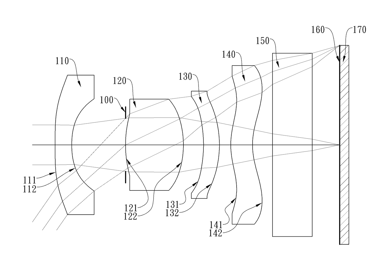
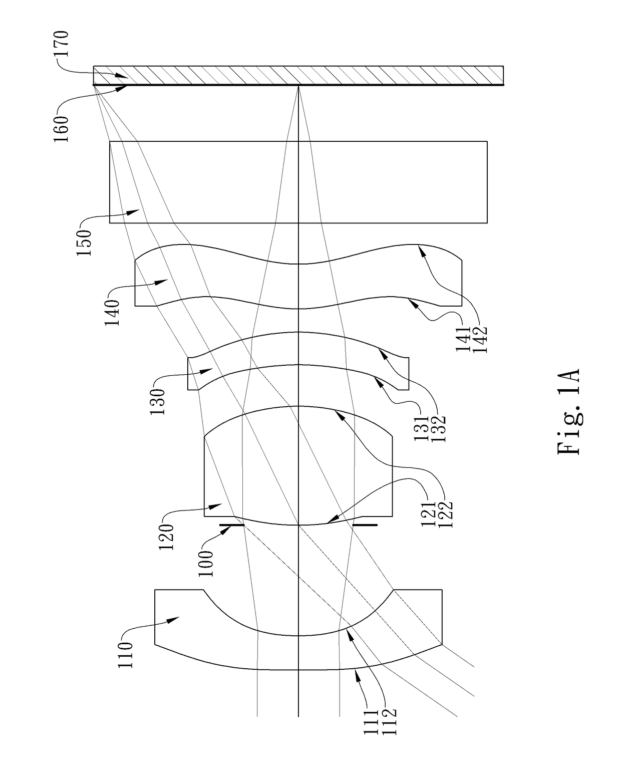
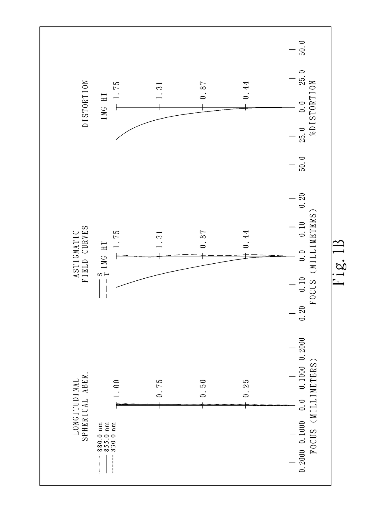
[0068]FIG. 1A is a schematic view of an image capturing apparatus according to the 1st embodiment of the present disclosure. FIG. 1B shows, in order from left to right, longitudinal spherical aberration curves, astigmatic field curves and a distortion curve of the image capturing apparatus according to the 1st embodiment.

[0069]In FIG. 1A, the image capturing apparatus comprises an optical lens assembly (not otherwise herein labeled) of the present disclosure and an image sensor 170. The optical lens assembly comprises, in order from an object side to an image side, a first lens element 110, an aperture stop 100, a second lens element 120, a third lens element 130, and a fourth lens element 140.

[0070]The first lens element 110 with negative refractive power has an object-side surface 111 being convex in a paraxial region thereof and an image-side surface 112 being concave in a paraxial region thereof, which are both aspheric, and the first lens element 110 is made of plastic material...

2nd embodiment

[0101]FIG. 2A is a schematic view of an image capturing apparatus according to the 2nd embodiment of the present disclosure. FIG. 2B shows, in order from left to right, longitudinal spherical aberration curves, astigmatic field curves and a distortion curve of the image capturing apparatus according to the 2nd embodiment.

[0102]In FIG. 2A, the image capturing apparatus comprises an optical lens assembly (not otherwise herein labeled) of the present disclosure and an image sensor 270. The optical lens assembly comprises, in order from an object side to an image side, a first lens element 210, an aperture stop 200, a second lens element 220, a third lens element 230, and a fourth lens element 240.

[0103]The first lens element 210 with negative refractive power has an object-side surface 211 being convex in a paraxial region thereof and an image-side surface 212 being concave in a paraxial region thereof, which are both aspheric, and the first lens element 210 is made of plastic material...

3rd embodiment

[0111]FIG. 3A is a schematic view of an image capturing apparatus according to the 3rd embodiment of the present disclosure. FIG. 3B shows, in order from left to right, longitudinal spherical aberration curves, astigmatic field curves and a distortion curve of the image capturing apparatus according to the 3rd embodiment.

[0112]In FIG. 3A, the image capturing apparatus comprises an optical lens assembly (not otherwise herein labeled) of the present disclosure and an image sensor 370. The optical lens assembly comprises, in order from an object side to an image side, a first lens element 310, an aperture stop 300, a second lens element 320, a third lens element 330, and a fourth lens element 340.

[0113]The first lens element 310 with negative refractive power has an object-side surface 311 being convex in a paraxial region thereof and an image-side surface 312 being concave in a paraxial region thereof, which are both aspheric, and the first lens element 310 is made of plastic material...


PUM


Abstract

This invention provides an optical lens assembly comprising, in order from an object side to an image side: a first lens element with negative refractive power having an image-side surface being concave in a paraxial region thereof; a second lens element having positive refractive power; a third lens element having an object-side surface being concave in a paraxial region thereof; and a fourth lens element having an object-side surface being convex in a paraxial region thereof and an image-side surface being concave in a paraxial region thereof, the image-side surface thereof having at least one convex shape in an off-axis region thereof; wherein the optical lens assembly has a total of four lens elements. With such configuration, the optical lens assembly of the present disclosure is characterized by a reduced size and a wide field of view.

Description

RELATED APPLICATIONS[0001]This application claims priority to Taiwan Application Serial Number 105110720, filed on Apr. 6, 2016, which is incorporated by reference herein in its entirety.BACKGROUNDTechnical Field[0002]The present disclosure relates to an optical lens assembly and an image capturing apparatus, and more particularly, to an optical lens assembly and an image capturing apparatus applicable to electronic devices.Description of Related Art[0003]With the miniaturization and diversification of electronic devices, the photographing module has a wide range of applications including various intelligent electronic devices, driving cameras, security surveillance cameras, 3D depth sensing devices (e.g. Time-of-Flight (TOF) cameras), and Human-Computer interaction (HCI) platforms. Accordingly, the demand for photographing modules with high-spec lens assemblies is increasing. Moreover, there is a trend in the market towards lens assemblies featuring a wide field of view and a compa...

Claims


Application Information

Patent Timeline
Patent Type & Authority Applications(United States)
IPC IPC(8): G02B13/00G02B13/04G02B27/00G02B9/34
CPCG02B13/004G02B27/0025G02B13/04G02B9/34
Inventor LIAO, LIN-YAOHUANG, HSIN-HSUANYANG, SHU-YUN
Owner LARGAN PRECISION
Why Eureka
Try Eureka