
Disc pulverizing mill

a technology of pulverizing mills and discs, which is applied in the field of pulverizing mills, can solve the problems of preventing the mill from operating properly, affecting the quality of the product, and causing damage to the mill

Inactive Publication Date: 2017-10-19
HUMMEL JAMES
View PDF9 Cites 3 Cited by
  • Summary
  • Abstract
  • Description
  • Claims
  • Application Information

AI Technical Summary

Benefits of technology

The patent describes a method and apparatus for cooling a disc mill with a rotating disc blade. The method involves drawing air through two material outlets along opposite tangents to the blade, and directing air streams along specific lines to cool the blade and pulverized material. The apparatus includes a disc mill housing with multiple material outlets and air inlets, as well as a mill door and a stationary blade assembly with a water jacket support and a rotating disc blade attached to a flywheel. The technical effects of the patent include improved cooling efficiency, reduced power consumption, and improved mill performance.

Problems solved by technology

One of the challenges in pulverizing materials is the production of heat as material is broken from larger particles into smaller particles.
If the pulverized material are allowed to get near or reach the melting temperature particles can agglomerate and form into a mass and damage the mill and prevent the mill from operating properly.
If the mill is supplying material for ongoing manufacturing, then the speed of the entire manufacturing process might need to be reduced because of the limitation of the disc mill to supply the needed pulverized material.

Method used


Image

  • Disc pulverizing mill
  • Disc pulverizing mill
  • Disc pulverizing mill

Examples


Embodiment Construction

[0022]In some embodiments a motor may be configured to rotate at a fixed operating speed. The introduction of material into the mill will cause resistance, which will increase the power or amps required to maintain the fixed speed of the motor. Disc mill systems often get too hot before the motor is at full power. This means that the motor is not working to full capacity most of the time. This also means that the throughput, or output of the mill over a time period is reduced based on the temperature limitations of the mill. Mills have areas in them that are hotter than other areas. When the temperature in a mill gets too high material may stick together or agglomerate. This is contrary to the purpose of the mill, as the purpose of the mill is to reduce the particle size of the material. If the hot material that has agglomerated exits out of the mill housing and cools without sticking to anything, it can be recycled back into the mill as a larger particle as described below. If the ...


PUM


Abstract

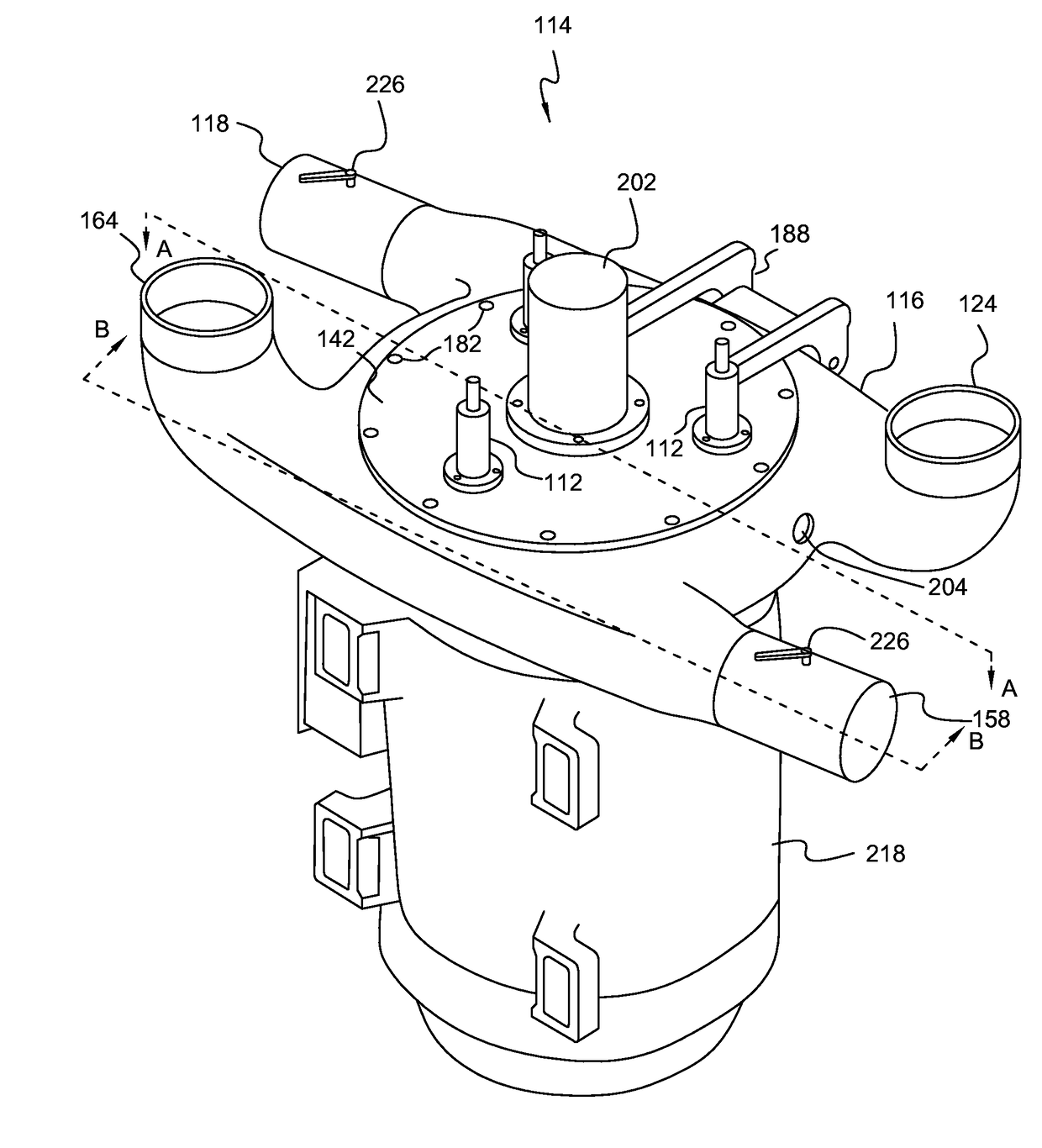
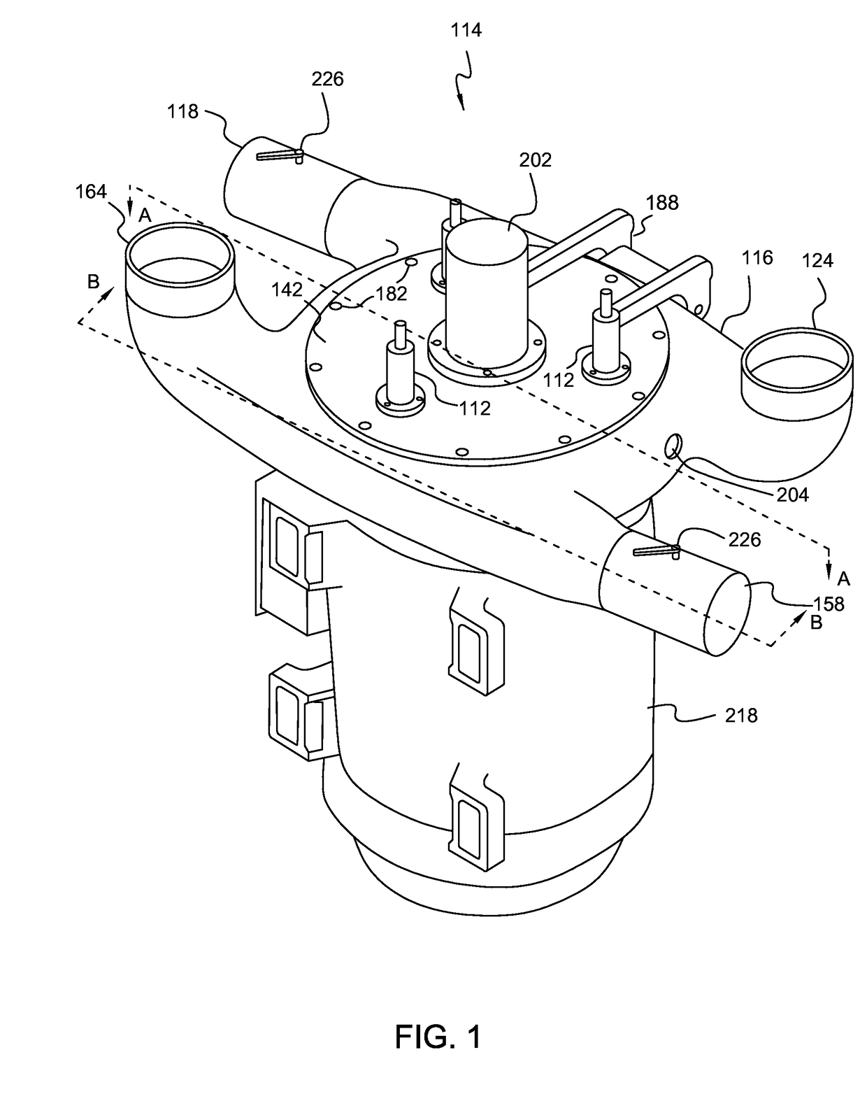
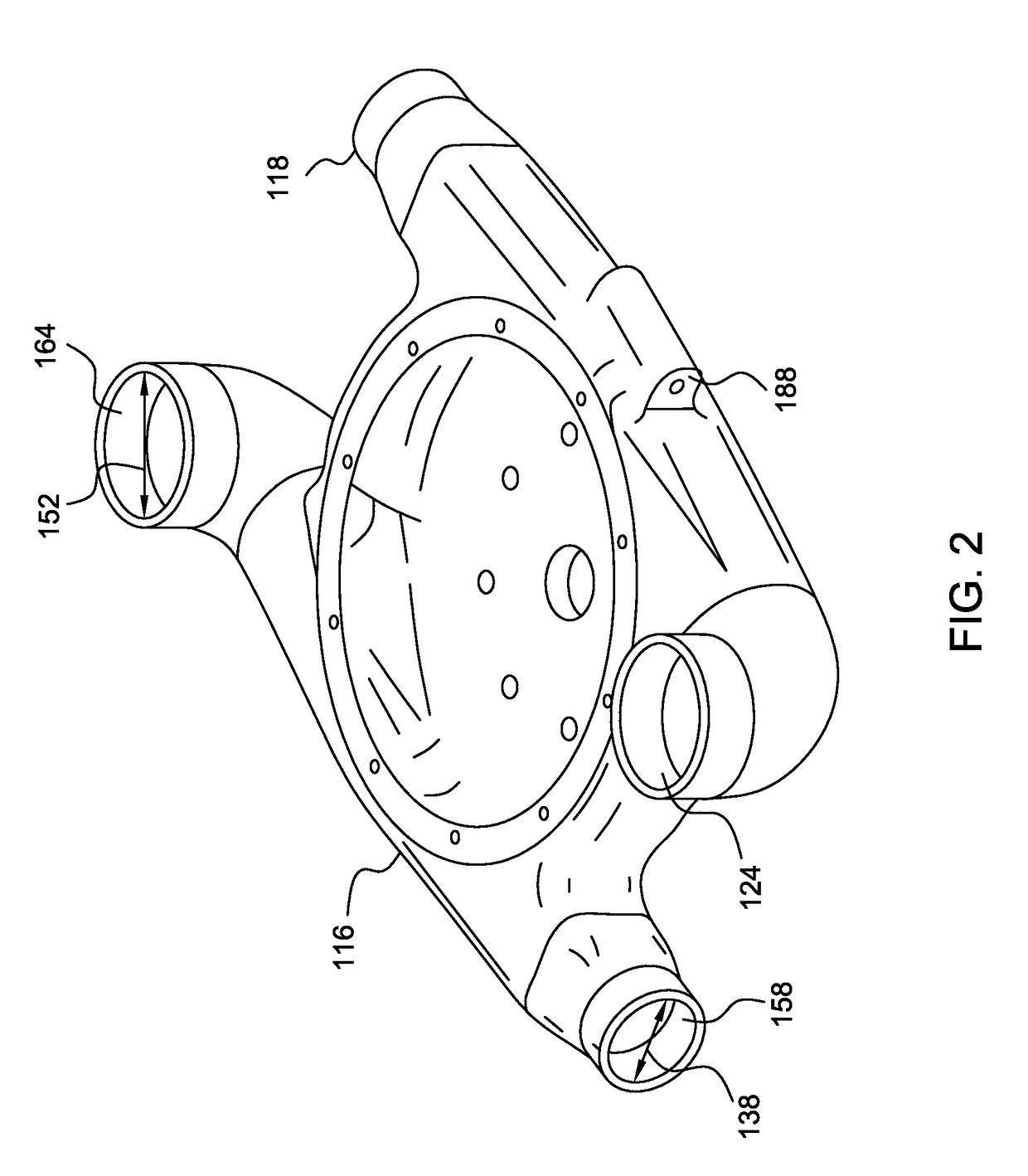
A method and system for of cooling a disc mill having a rotating disc blade is disclosed. A disc mill may have a first and second material outlet positioned generally along tangents to the rotating disc blade. Air may be drawn through the first and second material outlets. A disc mill may include first and second air inlets positioned generally along tangents to the rotating disc blade. The first and second inlets may direct air streams to cool a first and second portion of the rotating disc blade and pulverized material.

Description

BACKGROUND1. Technical Field[0001]This disclosure relates to machines for solid material comminution or disintegration with a rotary cooperating service, and specifically relates to disc pulverizing mills with opposed flat coaxial surfaces.2. Background Art[0002]Disc mills are used to pulverize raw material, such as plastics in pellet form, into a powder form to be used in a manufacturing process. One of the challenges in pulverizing materials is the production of heat as material is broken from larger particles into smaller particles. Each raw material will have a melting temperature. If the pulverized material are allowed to get near or reach the melting temperature particles can agglomerate and form into a mass and damage the mill and prevent the mill from operating properly.[0003]When the temperature in a disc mill approaches a melting point of the material, the temperature may be maintained or reduced by slowing the speed of material introduced into the mill. The result is a re...

Claims


Application Information

Patent Timeline
Patent Type & Authority Applications(United States)
IPC IPC(8): B02C7/17B02C7/08B02C7/14B02C25/00
CPCB02C7/17B02C25/00B02C7/14B02C7/08
Inventor HUMMEL, JAMES
Owner HUMMEL JAMES
Learn More