Method for generating control data, data processing device, machine tool, and program

a technology of control data and data processing device, applied in the field of generating control data, can solve the problem of more difficult to determine the appropriate tool path of the nozzl

Active Publication Date: 2017-10-19
MACHINE TOOL TECH RES FOUND +1
View PDF32 Cites 10 Cited by
  • Summary
  • Abstract
  • Description
  • Claims
  • Application Information

AI Technical Summary

Benefits of technology

[0005]The technology of Japanese Patent Laying-Open No. 2015-199197 is directed to the powder bed method. This method is suitable for a method for stacking thin films one by one. On the other hand, a shape can be more freely created by a method for cladding on a surface of a material by emitting laser while applying powders from a nozzle. However, it is more difficult to determine an appropriate tool path of the nozzle, which is three-dimensionally movable, as compared with a case of performing solidification for each layer (only in consideration of motion in a plane).

Problems solved by technology

However, it is more difficult to determine an appropriate tool path of the nozzle, which is three-dimensionally movable, as compared with a case of performing solidification for each layer (only in consideration of motion in a plane).

Method used


Image

  • Method for generating control data, data processing device, machine tool, and program
  • Method for generating control data, data processing device, machine tool, and program
  • Method for generating control data, data processing device, machine tool, and program

Examples


Embodiment Construction

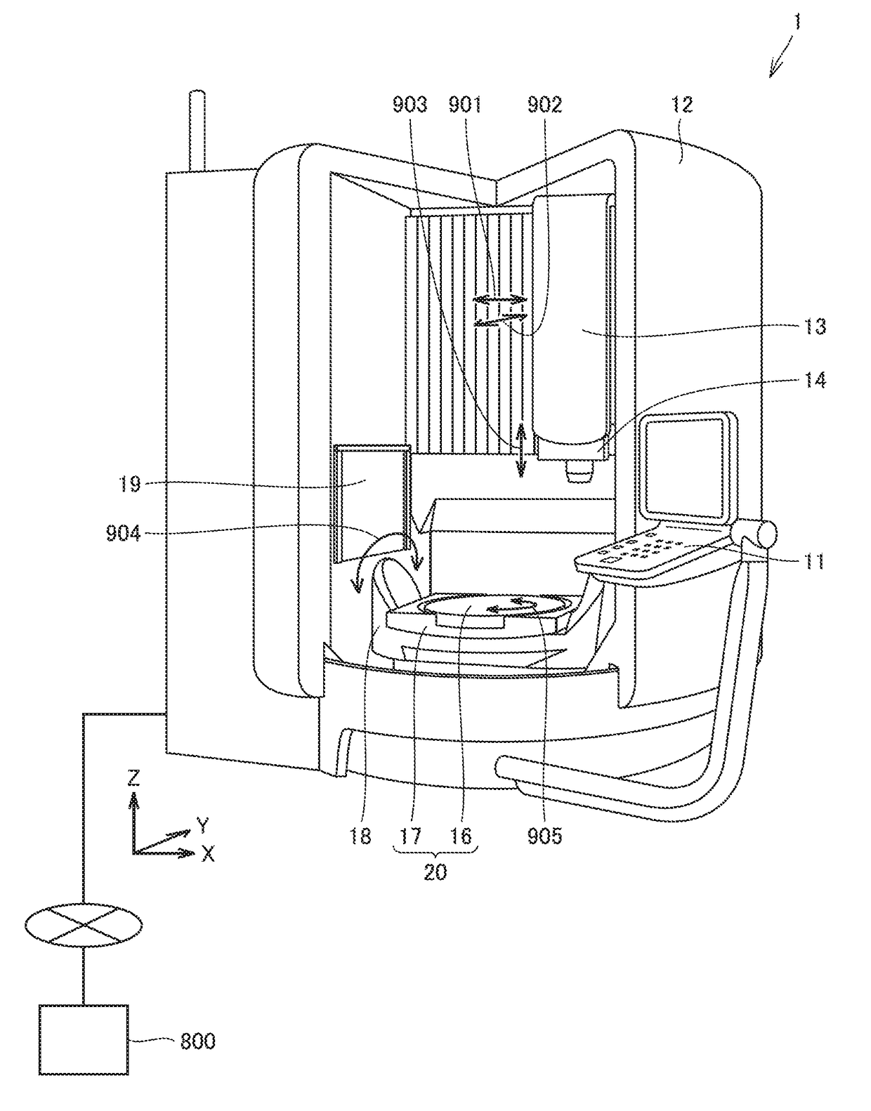
[0021]In the description below, it is assumed that a directed energy deposition method is used as an exemplary additive manufacturing process in the additive manufacturing technology. It should be noted that control data described below is used during additive manufacturing. Specifically, the control data is data for manufacturing a product having a designated shape using the additive manufacturing technology.

[0022]

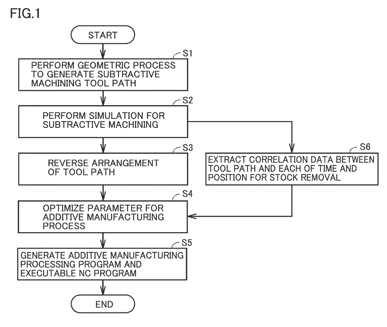
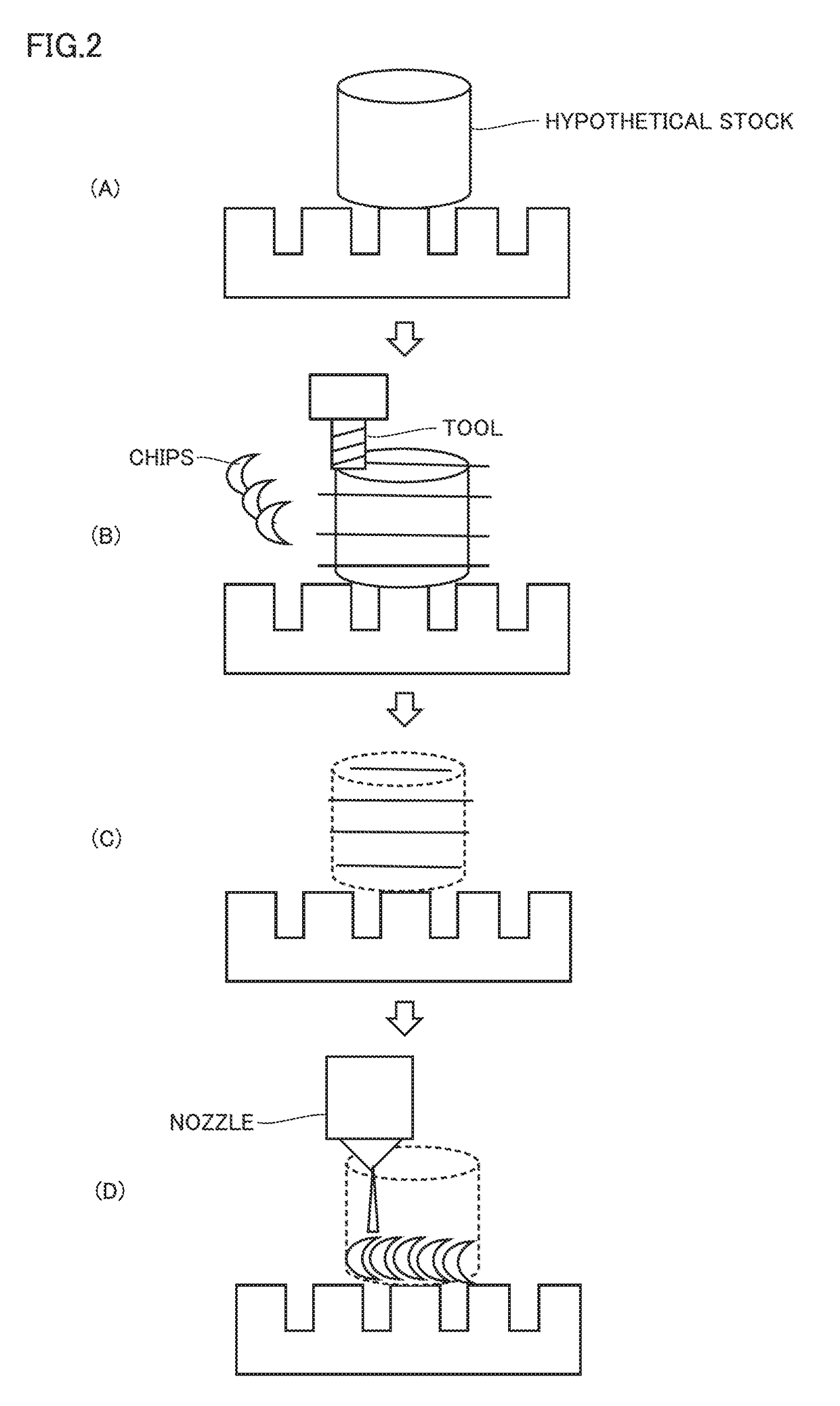
[0023]In the directed energy deposition method, a direction in which material powders (powders) are applied preferably corresponds to the gravity direction as much as possible. A path (hereinafter, also referred to as “tool path Pn”) of a nozzle for applying the powders is obtained by selecting a shape that can be perpendicular to the gravity direction. Tool path Pn (motion path; machining path) can be determined from the shape of a final product to be manufactured, as described below. Conventionally, an optimum value is determined through trial and error.

[0024]As one of ...


PUM

PropertyMeasurementUnit
shapeaaaaaaaaaa
motion speedaaaaaaaaaa
cylindrical shapeaaaaaaaaaa

Abstract

A method for generating control data is a method for generating control data for manufacturing a product having a designated shape using an additive manufacturing technology. The control data includes a path of a nozzle for supplying a material. The method for generating the control data includes: determining a cutting path for cutting the designated shape by a tool; and determining the path of the nozzle by reproducing the cutting path temporally reversely.

Description

BACKGROUND OF THE INVENTIONField of the Invention[0001]The present invention relates to a method for generating control data in an additive manufacturing technology.Description of the Background Art[0002]Conventionally, an additive manufacturing technology has been known. The additive manufacturing technology refers to a process of producing an object by adding a material based on a numeric representation of a three-dimensional shape. In many cases, the additive manufacturing technology is implemented by stacking layers on one another, and is in contrast to a subtractive manufacturing technology. It should be noted that the definition of such an additive manufacturing technology is provided in ASTM F2792-12a (Standard Terminology for Additive Manufacturing Technologies) of ASTM International, which is a private, standards development organization for industrial standards. In addition, the additive manufacturing technology is also referred to as “3D printer”.[0003]Japanese Patent Lay...

Claims


Application Information

Patent Timeline
Patent Type & Authority Applications(United States)
IPC IPC(8): B33Y50/02B33Y10/00B33Y30/00G05B19/4099
CPCB29C67/0088B29C67/0055B33Y10/00G05B2219/49023B33Y50/02G05B19/4099B33Y30/00B33Y50/00B29C64/153B29C64/188B29C64/106B29C64/386Y02P90/02
Inventor YAMAZAKICARTER, DAVIDFUJISHIMA, MAKOTOODA, YOHEI
Owner MACHINE TOOL TECH RES FOUND
Why Eureka
Try Eureka