
Method and system for decelerating a vehicle

a technology of deceleration and vehicle, applied in the field of vehicles, can solve the problems of dissipation of part of the work produced by the combustion engine, clutch slippage, difficulty in high-accuracy maneuvering of the vehicle at low speeds, etc., and achieve the effect of facilitating maneuvering of the vehicl

Active Publication Date: 2017-10-19
SCANIA CV AB
View PDF10 Cites 4 Cited by
  • Summary
  • Abstract
  • Description
  • Claims
  • Application Information

AI Technical Summary

Benefits of technology

This patent describes a system and method for maneuvering vehicles at low speeds with high accuracy. By using a clutch and an electrical machine, the vehicle can move smoothly and without sudden acceleration or deceleration. The driver only needs to use the accelerator and gearbox to move the vehicle, and the system ensures that the vehicle is always in a stationary state when decelerated. Overall, this system improves the efficiency and control of vehicles during maneuvering.

Problems solved by technology

It can, however, be difficult to perform high-accuracy maneuvering of the vehicle at low speeds when a clutch is used.
When maneuvering the vehicle at low speeds the output shaft of the combustion engine often rotates at a different (higher) speed than the gearbox input shaft, with the result that the clutch is slipping, i.e. the clutch is partially engaged, and part of the work produced by the combustion engine is dissipated as friction losses over the clutch.

Method used


Image

  • Method and system for decelerating a vehicle
  • Method and system for decelerating a vehicle
  • Method and system for decelerating a vehicle

Examples


Embodiment Construction

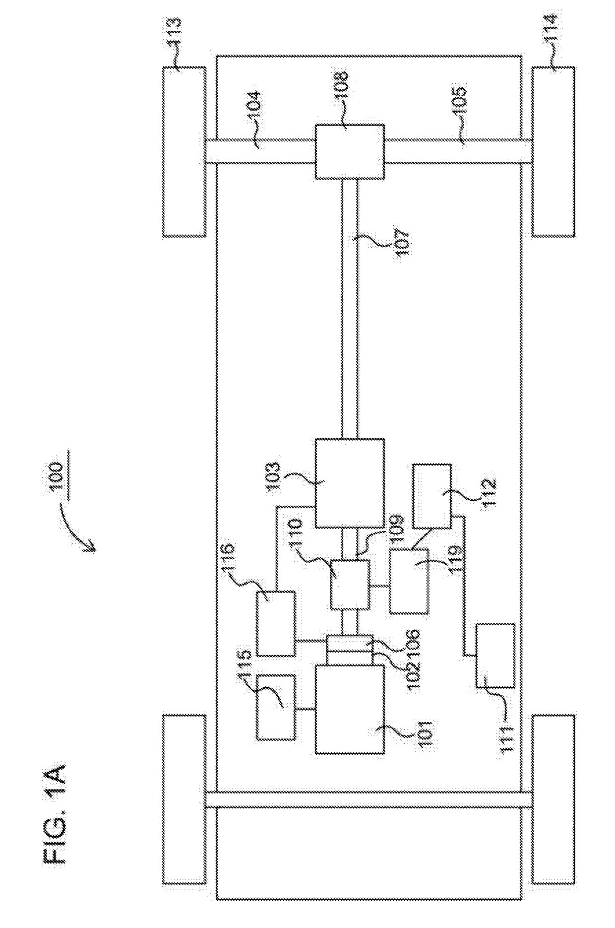
[0036]FIG. 1A schematically depicts a power train of an exemplary hybrid electric vehicle 100. The vehicle 100 in FIG. 1A is a parallel hybrid vehicle 100. The power train of the parallel hybrid vehicle in FIG. 1A comprises a combustion engine 101 which, in a conventional manner, is connected, via an output shaft of the engine 101, to a gearbox 103 via a clutch 106. The engine 101 is controlled by the vehicle's control system via a control unit 115. The clutch 106, which, for example, can be an automatically operated clutch, and the gearbox 103 are also controlled by the vehicle's control system by means of a control unit 116.

[0037]The vehicle also includes a hybrid portion with an electrical machine 110, which is connected to the input shaft 109 of the gearbox 103, downstream of the clutch 106, so that the gearbox input shaft 109 can be driven by the electrical machine 110 also when the clutch 106 is open, i.e. disengaged. Thereby, the parallel hybrid vehicle 100 can provide torque...


PUM


Abstract

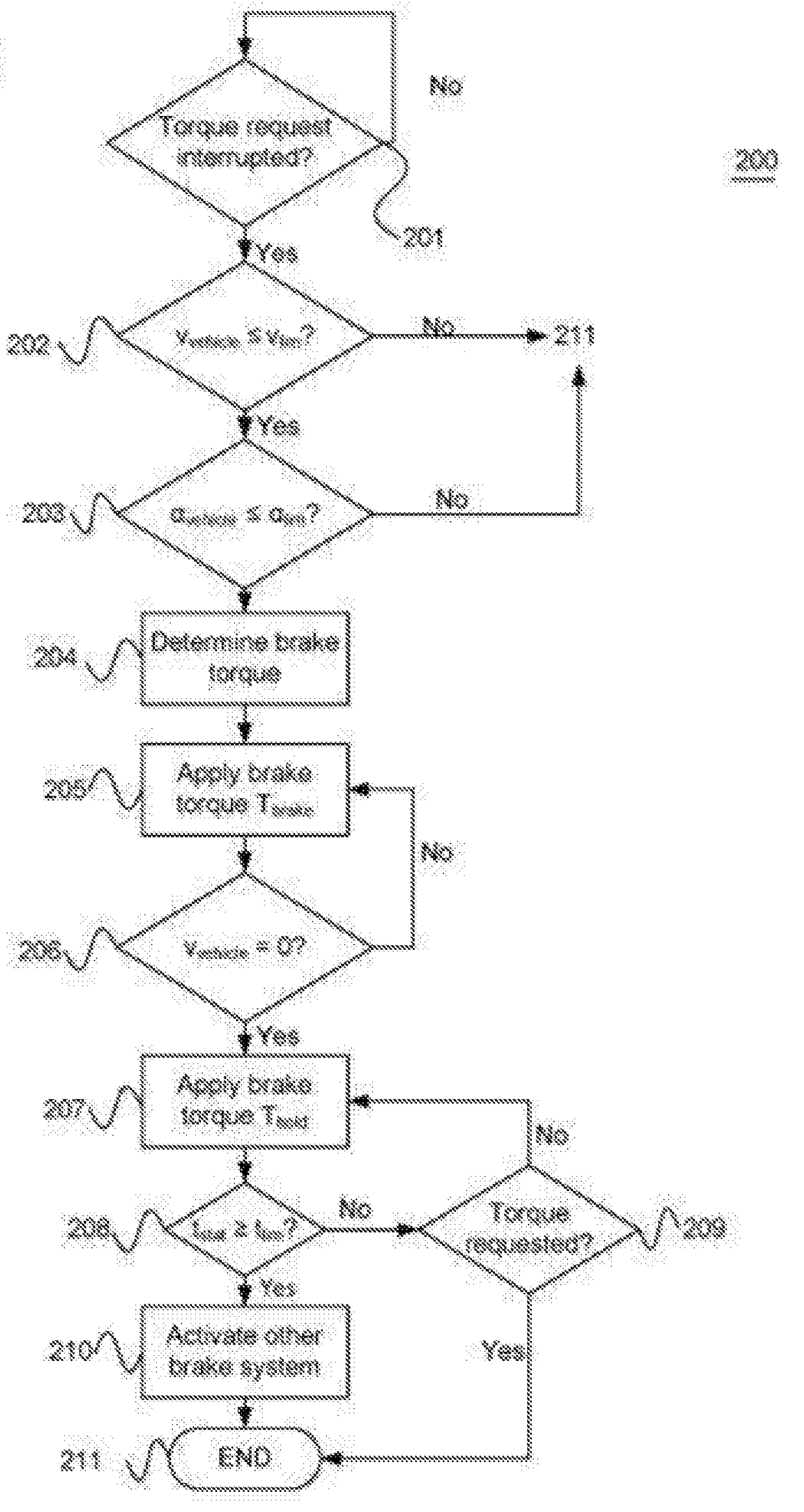
The present invention relates to a method for decelerating a vehicle comprising an electrical machine being arranged to provide a controllable torque to at least one drive wheel, said vehicle including driver controllable means for actively requesting a torque for propelling the vehicle. The method includes, when a driver request for a propelling torque is reduced at least to a first extent: applying a first brake torque by means of said electrical machine, by means of said first brake torque, decelerate said vehicle to a stationary state, and by means of said electrical machine, when said vehicle has been decelerated to said stationary state, continue applying a torque by means of said electrical machine to keep said vehicle in said stationary state.

Description

CROSS-REFERENCE TO RELATED APPLICATION(S)[0001]This application is a national stage application (filed under 35 §U.S.C. 371) of PCT / SE15 / 051089, filed Oct. 15, 2015 of the same title, which, in turn claims priority to Swedish Application No. 1451290-9 filed Oct. 29, 2014 of the same title; the contents of each of which are hereby incorporated by reference.FIELD OF THE INVENTION[0002]The present invention relates to vehicles, and in particular to a method and system for decelerating a vehicle. The present invention also relates to a vehicle, as well as a computer program product that implement the method according to the invention.BACKGROUND OF THE INVENTION[0003]With regard to vehicles in general, and at least to some extent heavy / commercial vehicles, such as trucks, buses and the like, there is constantly ongoing research and development with regard to increasing fuel efficiency and reducing exhaust emissions.[0004]This is often at least partly due to growing governmental concern i...

Claims


Application Information

Patent Timeline
Patent Type & Authority Applications(United States)
IPC IPC(8): B60W20/15B60L15/20B60W10/08B60W30/18B60W10/06
CPCB60W20/15B60W10/08B60W10/06B60W30/18109B60W30/18054B60L15/2009Y10S903/903B60W2540/12B60W2710/083B60W2710/0666B60W2720/10B60L2240/12B60L2240/423B60W2540/10B60W30/18118B60W2300/10B60W2300/12B60W2530/10B60K6/387B60W50/10B60W10/184B60W20/00B60W30/181B60K2006/4825B60W2510/0225B60W2552/15Y02T10/62Y02T10/72B60K6/48B60W10/18B60W30/18127B60T2270/60
Inventor AFRAM, KOURIELIWELL, MATSNILSSON, MATTIASSUNDEN, FREDRIK
Owner SCANIA CV AB
Learn More