Cable tie

a cable tie and loop technology, applied in the field of cable tie, can solve the problems of shrinking of the loop, unable to expand the loop, and unable to meet the requirements of enlarging the loop, so as to reduce the space requirement, simplify the structure, and optimize the space requirement

Active Publication Date: 2017-10-19
SES STERLING IND HLDG AG
View PDF2 Cites 2 Cited by
  • Summary
  • Abstract
  • Description
  • Claims
  • Application Information

AI Technical Summary

Benefits of technology

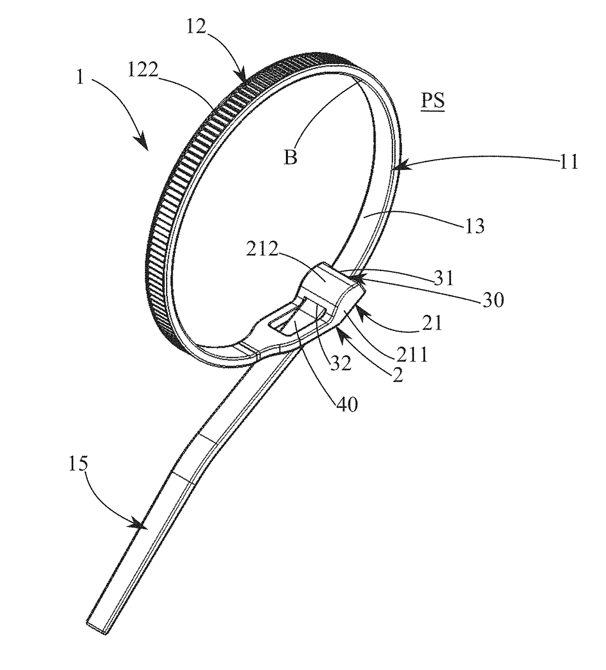
[0007]The present invention aims to overcome these disadvantages by offering a cable tie with a simplified structure and optimized space requirement, so that the fastening head shows a reduced space requirement outside of the loop in the tying position while ensuring the guidance of the free end of the material strip towards the outside of the loop when the cable tie is closed in a loop, regardless of the diameter of the loop.
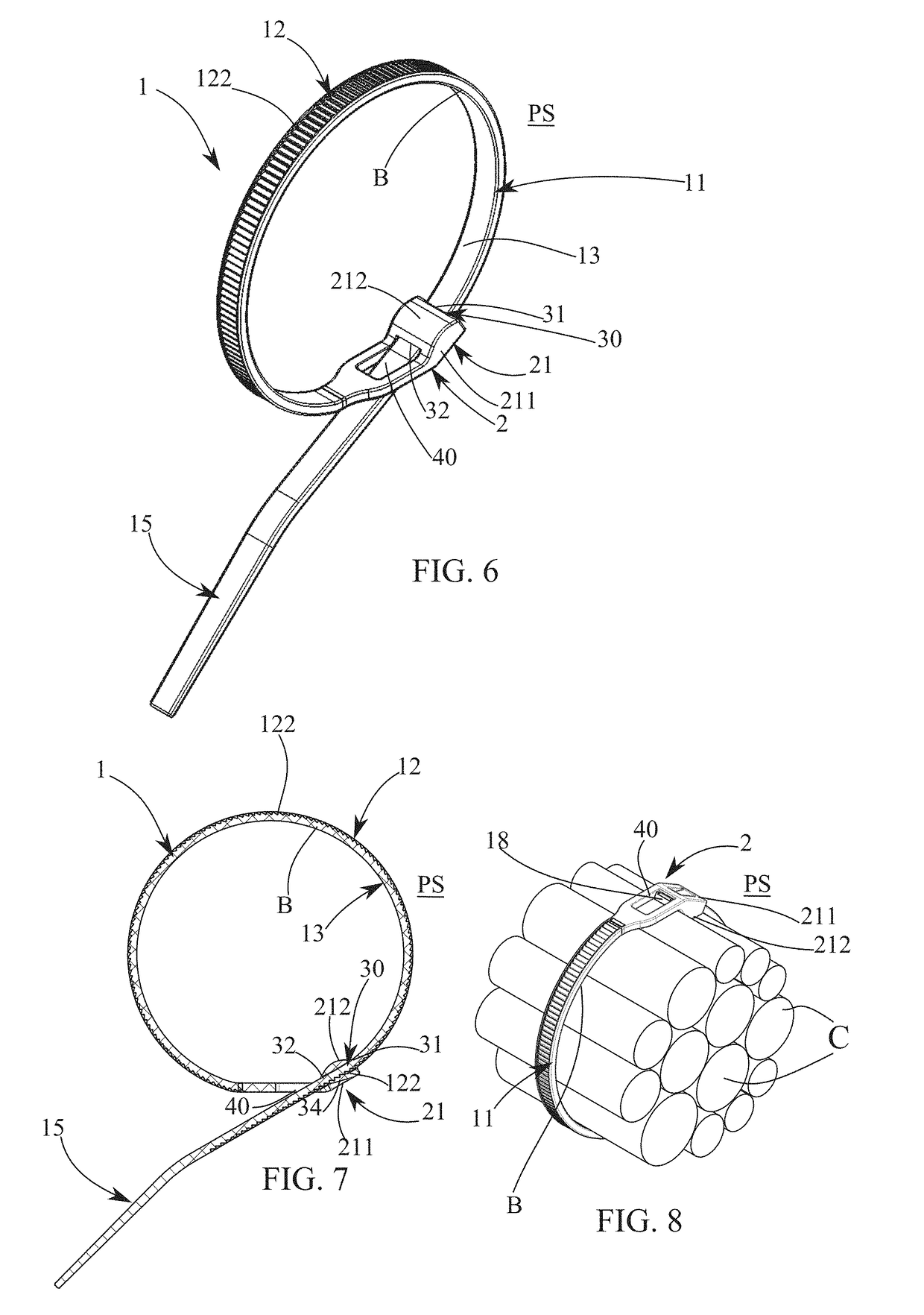
[0009]Adding a second opening allows designing a cable tie with a fastening head that protrudes mainly inside of the loop in the tying position. In fact, the second opening allows passing the free end of the material strip from the inside of the loop to the outside of the loop in the tying position. Moreover, the inclination angle given to the protruding section of the fastening head, and consequently to the first opening, allows guiding naturally and automatically the free end through the second opening towards the outside of the loop.

Problems solved by technology

In fact, when one pulls the second end of the material strip, the loop formed shrinks and it is no longer possible to enlarge the loop.
Nevertheless, the fastening head remains protruding outside of the loop and, in certain conditions, its presence is problematic.
In particular, such as when there are several cable harnesses, where the protruding fastening heads can damage the neighboring cables by crushing the insulations.
However, the implementation of this solution is difficult and time-consuming, as it requires, to close the cable tie in a loop around a cable harness, to introduce the free end of the material strip first in the first slot from the outside towards the inside of the harness, then in the second slot, from the inside towards the outside of the harness.
Therefore, the structure of this cable tie type is complex and does not necessarily guarantee the exit of the free end towards the outside, depending on the diameter of the loop.
For these reasons, the solutions of the prior art are not satisfying.

Method used


Image

  • Cable tie
  • Cable tie
  • Cable tie

Examples


first embodiment

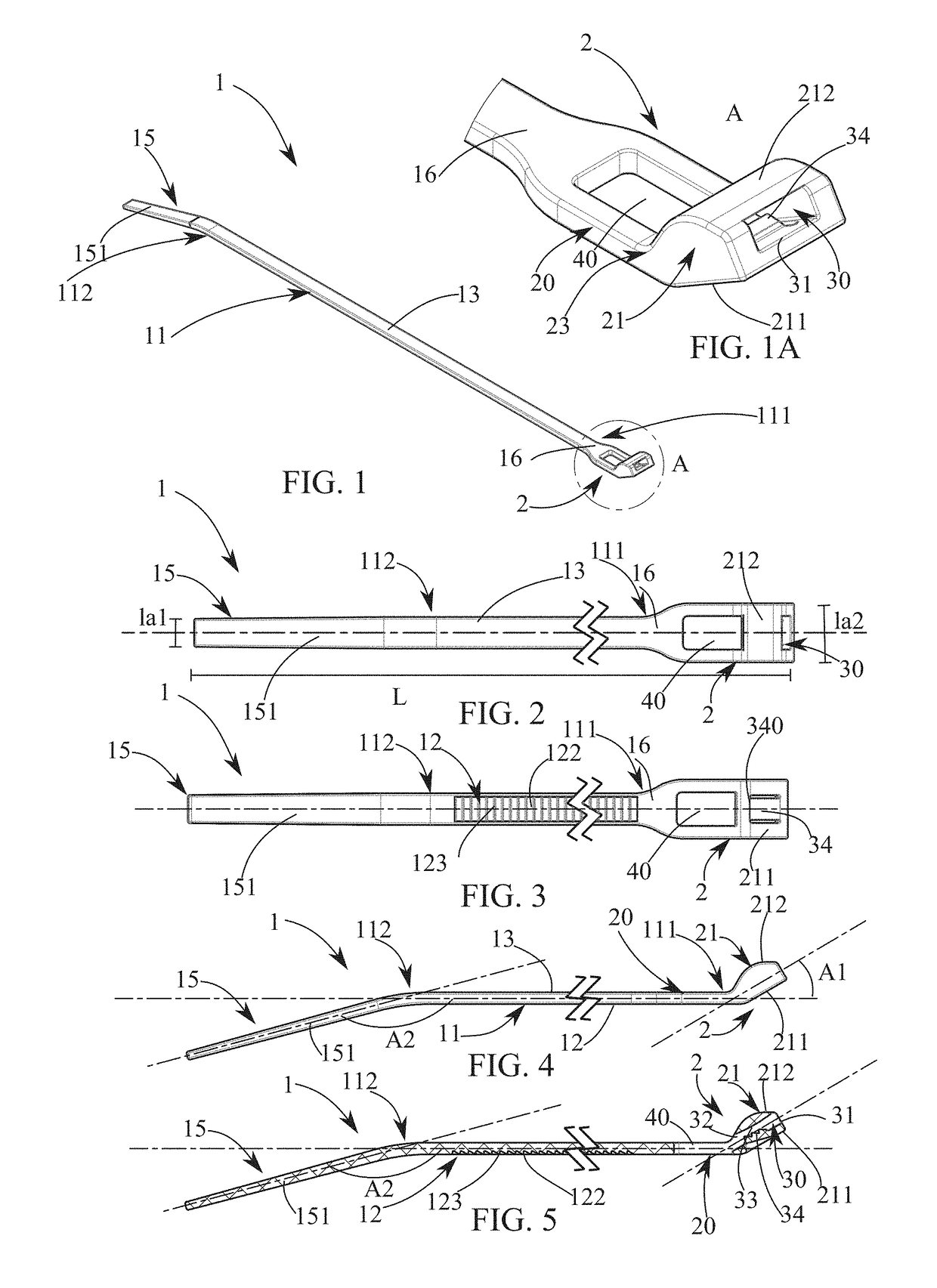
[0049] variant illustrated in FIGS. 1 to 8, cable tie 1 is an elongate element with a length L, which comprises a material strip 11 with a width la1, which is flexible and has a substantially flat shape, having a first side 12 comprising a notched section 122 provided with a plurality of teeth 123 arranged to cooperate with a ratchet 34 described below, and a substantially smooth second side 13 opposite to first side 12, without this example being restrictive. In fact, second side 13, which is opposite to first side 12, could also comprise a notched section provided with a plurality of teeth, arranged to cooperate with an additional ratchet, in compliance with the variant illustrated in FIGS. 18 to 21.

[0050]Cable tie 1 comprises at a first end 111 of material strip 11 a fastening head 2 and comprises at an opposite second end 112 of material strip 11 an insertion element 15 that is free and intended for being inserted in fastening head 2. Insertion element 15 comprises an inclined s...

fourth embodiment

[0062]Advantageously and in compliance with this fourth embodiment variant, the arrangement of smooth second side 13 outside of loop B makes cleaning cable tie 120 easier and avoids the creation of catch-on areas.

[0063]According to a fifth variant represented in FIGS. 18 to 21, cable tie 130 differs from the first variant in that second side 13 also comprises a notched section 132. From this results that first side 12 and second side 13 of material strip 11 are notched. Moreover, fastening head 2 comprises two ratchets 34, 134, a first ratchet 34 intended for cooperating with notched section 122 of first side 12 and a second ratchet 134 intended for cooperating with notched section 132 of second side 13. In this case first ratchet 34 is arranged on internal side 33, on the side of first external wall 211, and second ratchet 134 is arranged on internal wall 33, on the side of second external wall 212. First ratchet 34 and second ratchet 134 are arranged in front of each other. Advant...


PUM


Abstract

A cable tie (1) having a material strip (11), a fastening head (2) that has a first opening (30) provided with a ratchet (34) and protrudes with respect to the longitudinal axis of material strip (11), an insertion element (15) arranged to be introduced in the fastening head (2), first opening (30) passing longitudinally through the fastening head (2) between an entry (31), at a free end of fastening head (2), and an exit (32), ending towards a junction area (16) between material strip (11) and fastening head (2). The fastening head (2) has a second opening (40) that passes transversely therethrough and arranged between junction area (16) and the first opening (30) so that, during a tying position of the cable tie (1), the exit (32) of first opening (30) ends inside of the loop and faces towards second opening (40).

Description

[0001]This application claims priority from French patent application serial no. 16 / 53365 filed Apr. 15, 2016.FIELD OF THE INVENTION[0002]The present invention relates to a cable tie including an elongate flexible material strip provided with a first side and a second side, which are opposite, said first side comprising a notched section, said cable tie comprising at a first end of the material strip a fastening head comprising a first opening provided with a ratchet and which protrudes with respect to the longitudinal axis of the material strip, and at a second end of the material strip an insertion element that is free and arranged to be introduced in said fastening head, the first opening passing longitudinally through said fastening head between an entry ending at a free end of the fastening head and an exit ending towards a junction area between the material strip and the fastening head, cable tie wherein, in a tying position of said cable tie, said material strip passes throug...

Claims


Application Information

Patent Timeline
Patent Type & Authority Applications(United States)
IPC IPC(8): B65D69/00F16B1/02
CPCF16B1/02B65D69/00B65D63/1027B65D63/1072
Inventor ROLLIER, DANIEL
Owner SES STERLING IND HLDG AG
Why Eureka
Try Eureka