
System and method for increasing the responsiveness of a duct fired, combined cycle, power generation plant

a combined cycle and power generation plant technology, applied in steam engine plants, machines/engines, mechanical equipment, etc., can solve the problems of increasing the cost of operation increasing the cost of simple cycle power plants, and increasing so as to increase the net output of the combined cycle power generation plant faster, increase the responsiveness of duct firing, and quickly change the effect of outpu

Active Publication Date: 2017-10-19
SIEMENS ENERGY GLOBAL GMBH & CO KG +1
View PDF2 Cites 0 Cited by
  • Summary
  • Abstract
  • Description
  • Claims
  • Application Information

AI Technical Summary

Benefits of technology

The patent describes a system and method for increasing the responsiveness of a power generation plant that uses gas turbine engines and steam turbine engines. By operating the gas turbine engines at a lower load condition and using supplemental burners to provide additional heat, the system can quickly change output to meet changes in demand. The combined cycle power generation plant can adjust its output within a matter of minutes, making it more flexible and efficient. This system can increase or decrease output by as much as 30 megawatts per minute. Overall, the patent provides a solution for power generation plants to quickly adapt to changes in demand and improve their overall efficiency.

Problems solved by technology

One of the challenges in the use of renewable energy is that the renewable energy source must be supplemented by using energy storage to prevent supply gaps due to its intermittent and unpredictable nature.
Another challenge is the need for electricity to heat and cool homes during the different seasons as well as the operating strategy of various sections of a power grid.
The seasonal use of power does not necessarily match up with the availability of power from renewable resources.
Such is especially true where a financial penalty is applicable when a power plant cannot reach a load requested by power grid operators.
While simple cycle power plants are capable of fast changes in output, the simple cycle power plants cost more to operate as their overall efficiency is below that of a combined cycle plant and environmental considerations such as emissions associated with the installation of a simple cycle power plant can undermine their viability.
This system has a slow response time because the system is thermodynamically limited by the time required for the additional steam to be generated and the steam turbine engines to respond with greater output once the additional steam input is received.
However, power grid controllers are more often requesting a ramp up rate far faster than five megawatts per minute.

Method used


Image

  • System and method for increasing the responsiveness of a duct fired, combined cycle, power generation plant
  • System and method for increasing the responsiveness of a duct fired, combined cycle, power generation plant
  • System and method for increasing the responsiveness of a duct fired, combined cycle, power generation plant

Examples


Embodiment Construction

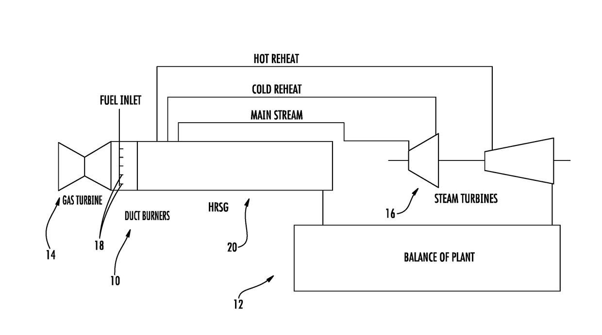
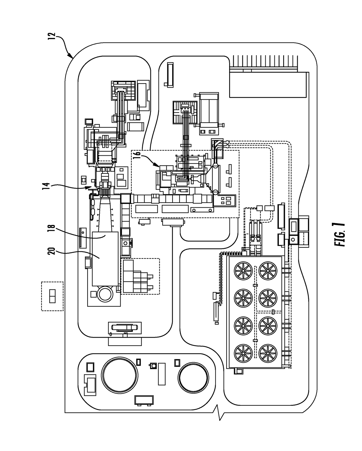
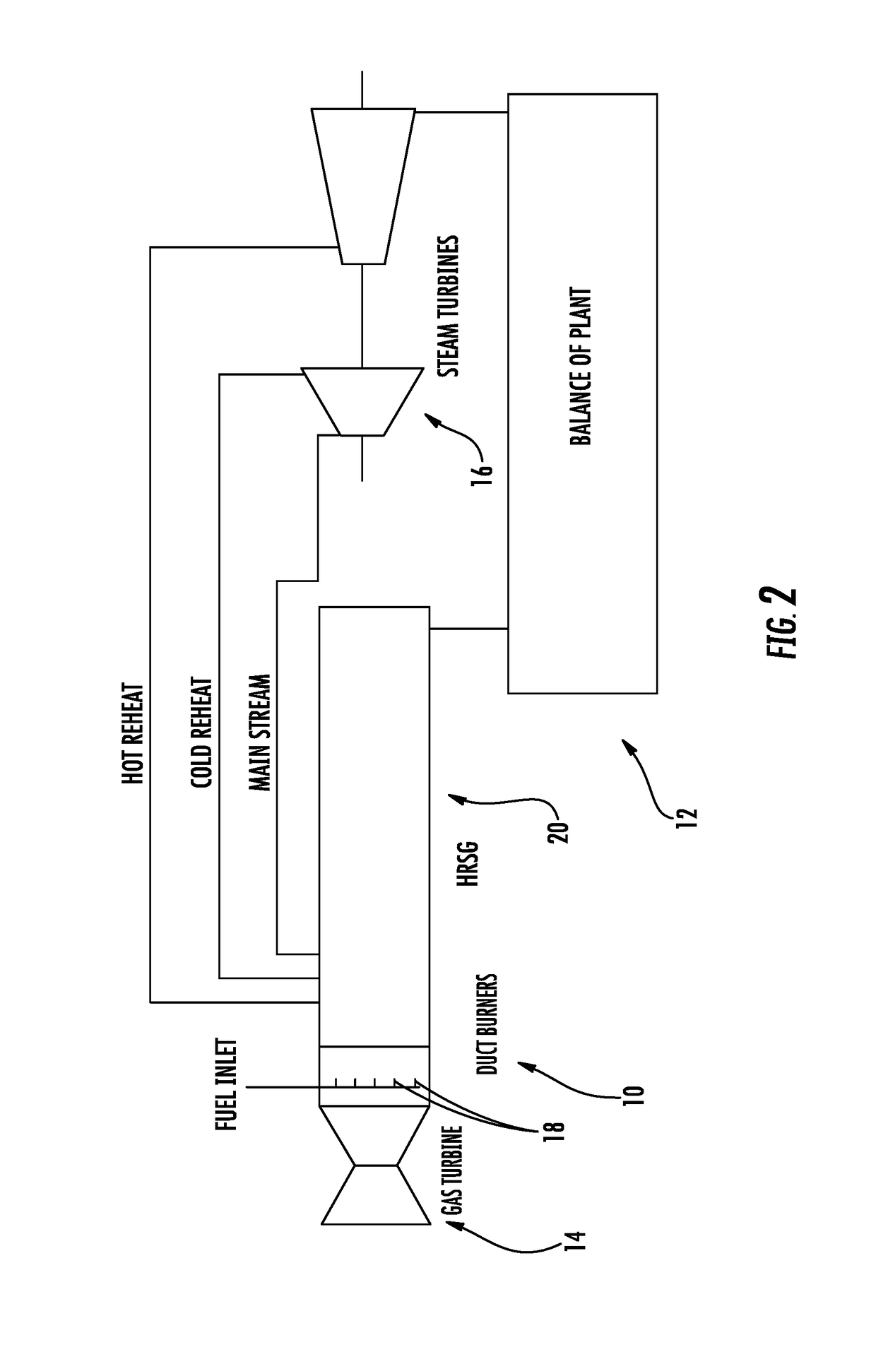
[0018]As shown in FIGS. 1-5, a system 10 and method for increasing the responsiveness of a duct fired, combined cycle power generation plant 12 via operating one or more gas turbine engines 14 at a part load condition less than 100 percent load, one or more steam turbine engines 16, and one or more supplemental burners 18 providing additional heat to a heat recovery steam generator 20 upstream from the steam turbine engine 16 is disclosed. The combination of the steam turbine engines 16 and supplemental burners 18 operating together with gas turbine engines 14 at a part load condition enables the system 10 to quickly change output to accommodate changes in output demand of the duct fired, combined cycle power generation plant 12. By operating the one or more gas turbine engines 14 at a part load condition, the gas turbine engines 14 are able to be used to increase net output of the combined cycle power generation plant 12 faster than relying on increasing output via duct firing.

[001...


PUM


Abstract

A system and method for increasing the responsiveness of a duct fired, combined cycle power generation plant (12) via operating one or more gas turbine engines (14) at a part load condition less than 100 percent load, one or more steam turbine engines (16), and one or more supplemental burners (18) providing additional heat to a heat recovery steam generator (20) upstream from the steam turbine engine (16) is disclosed. The combination of the steam turbine engines (16) and supplemental burners (18) operating together with gas turbine engines (14) at a part load condition enables the system to quickly change output to accommodate changes in output demand of the duct fired, combined cycle power generation plant (12). By operating the one or more gas turbine engines (14) at a part load condition, the gas turbine engines (14) are able to be used to increase net output of the combined cycle power generation plant (12) faster than relying on increasing output via duct firing.

Description

FIELD OF THE INVENTION[0001]The present invention is directed generally to gas turbine systems, and more particularly to duct fired, combined cycle power generation plants.BACKGROUND OF THE INVENTION[0002]Over the past decade, an increasing amount of renewable energy supply has been added to the power grids of major markets, such as the United States and Europe. One of the challenges in the use of renewable energy is that the renewable energy source must be supplemented by using energy storage to prevent supply gaps due to its intermittent and unpredictable nature. Another challenge is the need for electricity to heat and cool homes during the different seasons as well as the operating strategy of various sections of a power grid. The seasonal use of power does not necessarily match up with the availability of power from renewable resources. With all these influencing factors on the electrical power supply, combined cycle power plants must be able to ramp up and down quickly to resp...

Claims


Application Information

Patent Timeline
Patent Type & Authority Applications(United States)
IPC IPC(8): F01K23/10
CPCF01K23/105F01K23/101Y02E20/16
Inventor FARQUHARSON, MARLON H.JOHNSON, RAY L.SCHEURLEN, MICHAELHANSEL, MONICA B.SHARP, JAMES H.OOSTENDORP-KRAMER, KARIN MARJAN
Owner SIEMENS ENERGY GLOBAL GMBH & CO KG
Learn More