Illumination apparatus and projection display apparatus using the same

a technology of projection display and projection apparatus, which is applied in the direction of lighting and heating apparatus, instruments, optical elements, etc., can solve the problems of low light use efficiency, and low light conversion efficiency, and achieve the effect of reducing the decrease in light use efficiency

Active Publication Date: 2017-10-19
CANON KK
View PDF4 Cites 3 Cited by
  • Summary
  • Abstract
  • Description
  • Claims
  • Application Information

AI Technical Summary

Benefits of technology

[0008]Accordingly, the present invention provides an illumination apparatus that can reduce a decrease in light use efficiency caused by ...

Problems solved by technology

The resulting brightness saturation phenomenon may lower the efficiency of light conversion, and the level of brightness may not increase in proportion to the increase in t...

Method used


Image

  • Illumination apparatus and projection display apparatus using the same
  • Illumination apparatus and projection display apparatus using the same
  • Illumination apparatus and projection display apparatus using the same

Examples


first embodiment

[0025]A configuration of an illumination apparatus and a projection display apparatus according to a first embodiment of the present invention will be described with reference to FIG. 1 to FIGS. 6A and 6B.

(Configuration of Illumination apparatus and Projection Display Apparatus)

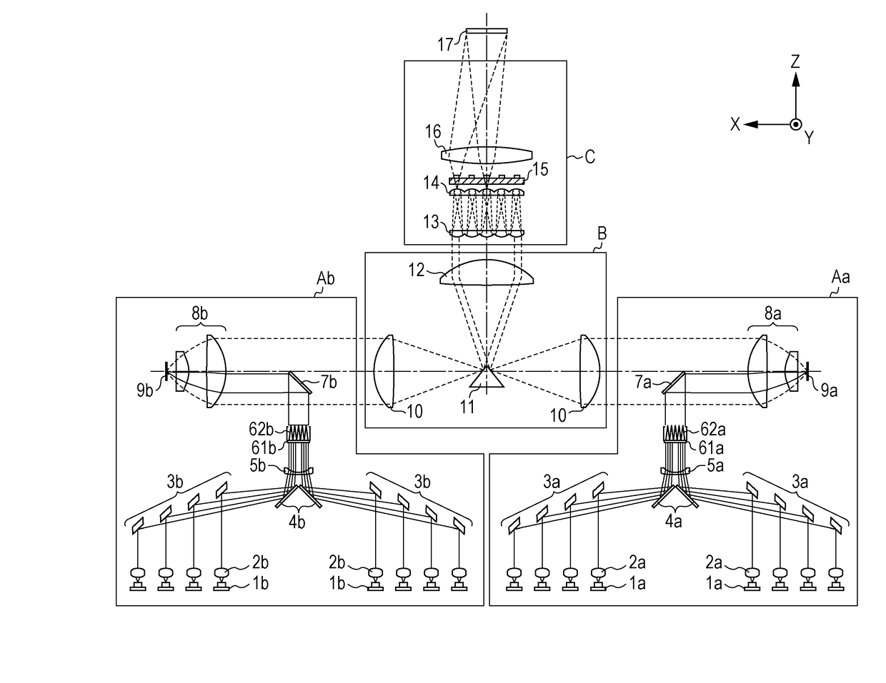
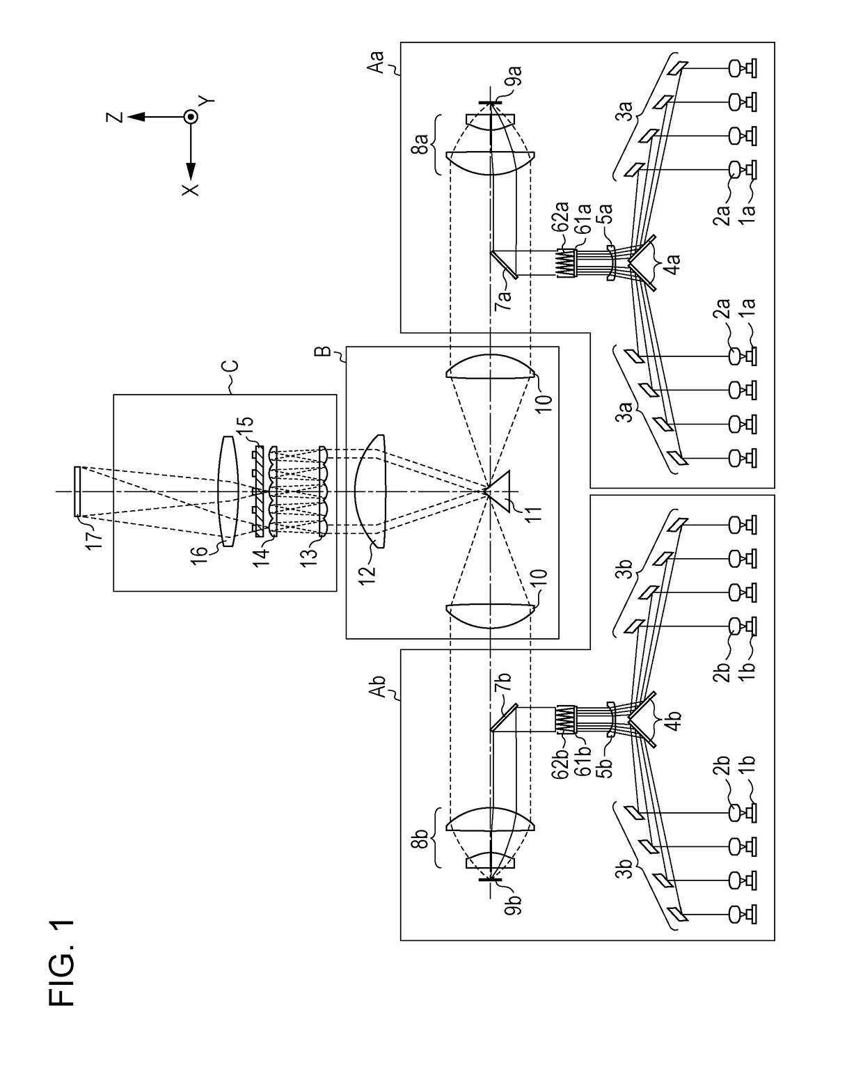
[0026]FIG. 1 illustrates a configuration of an illumination apparatus according to the present embodiment.

[0027]In the drawings, a direction parallel to the optical axis of each collimator lens 2 (2a, 2b) described below is defined as a Z-axis direction. A direction orthogonal to the Z-axis direction and determined such that a cross-section parallel to the optical axis of each light collecting lens unit 8 (8a, 8b) described below and the Z-axis direction is an XZ cross-section is defined as an X-axis direction. That is, the optical axis of the collimator lens 2 and the optical axis of the light collecting lens unit 8 do not necessarily need to be orthogonal to each other. A direction orthogonal to the Z-axis ...

third embodiment

[0093]FIG. 9 illustrates a configuration of an illumination apparatus according to a third embodiment of the present invention. A difference from the first embodiment is that the illumination apparatus of the third embodiment does not include the polarization conversion element 15. Another difference is that instead of using the light modulation element 17, which is a liquid crystal display element, the illumination apparatus of the present embodiment uses a light modulation element 171 which is a micromirror array including a plurality of micromirrors, each having an angle-adjustable reflective surface.

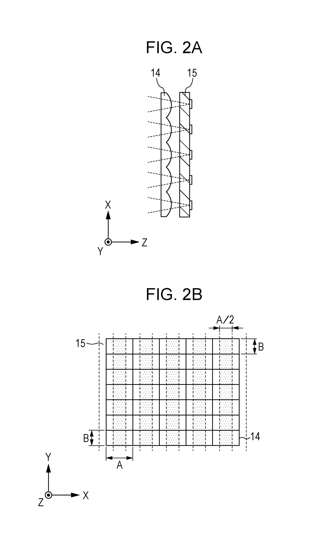
[0094]In the present embodiment, the illumination optical system C does not include the polarization conversion element 15, and uses the light modulation element 171 which is a micromirror array. In this case, each effective region in the illumination optical system C is a region on each lens cell of the second fly-eye lens 14. Each lens cell of the second fly-eye lens 14 is similar ...

fourth embodiment

[0098]FIG. 11 illustrates a configuration of an illumination apparatus according to a fourth embodiment of the present invention. A difference from the first embodiment is that instead of using the light modulation element 17, which is a liquid crystal display element, the illumination apparatus of the present embodiment uses the light modulation element 171 which is a micromirror array including a plurality of micromirrors, each having an angle-adjustable reflective surface. Accordingly, the shape of lens surfaces of a first lens surface array 251 (251a, 251b) and a second lens surface array 252 (252a, 252b) is different from that in the first embodiment.

[0099]In the present embodiment, a rod integrator 26 is disposed immediately after the combining prism 11 of the optical-path combining system B. Therefore, light source images formed by light beams from the two light source units A are formed in the vicinity of the vertex of the combining prism 11 and directly enter a light incide...


PUM


Abstract

An illumination apparatus includes an illumination optical system configured to illuminate a light modulation element; a plurality of light source units each including a fluorescent member, at least one light source, and a light-guiding optical system; and an optical-path combining system. A predetermined region in an area where light source images are formed by the illumination optical system using light beams from the optical-path combining system is defined as an effective region, and the number of the light source units is denoted by N. In this case, the light source images and N subregions obtained by dividing the effective region by N along a first side direction of the effective region or a second side direction orthogonal to the first side direction satisfy a predetermined relation.

Description

BACKGROUND OF THE INVENTIONField of the Invention[0001]The present invention relates to an illumination apparatus and a projection display apparatus using the same.Description of the Related Art[0002]In recent years, so-called solid-state light source projectors have been developed, which are configured to apply light emitted from a laser diode (hereinafter referred to as LD) as exciting light to a fluorescent member and use wavelength-converted fluorescent light as source light. Like projectors of the related art which use a mercury lamp as a light source, the solid-state light source projectors require brightness. As a technique for realizing brighter solid-state light source projectors, a technique described in U.S. Patent Application Publication No. 2014 / 0211170 is known.[0003]U.S. Patent Application Publication No. 2014 / 0211170 discloses a configuration which includes two light source units, each including blue LDs and a fluorescent member and capable of emitting a white light ...

Claims


Application Information

Patent Timeline
IPC IPC(8): G03B33/12G03B21/20G03B21/00G02B27/28G02B27/14G02B27/12F21V9/16F21V7/06F21V7/00
CPCG03B33/12G03B21/2066G03B21/204G03B21/006G03B21/008F21V7/06G02B27/141G02B27/126G02B27/283F21V9/16F21V7/0083G03B21/2073G03B21/208G03B21/2013H04N9/3152H04N9/3161H04N9/3164G03B21/005H04N9/3158
Inventor KAWASUMI, TAKEHITO
Owner CANON KK
Why Eureka
Try Eureka