
Light emitting diode with high efficiency

a light-emitting diode and high-efficiency technology, applied in the field of light-emitting diodes, can solve the problems of increasing light loss, reducing external quantum efficiency, and drooping, and achieves the effects of suppressing drooping, improving luminous efficacy, and reducing current density

Active Publication Date: 2017-10-19
SEOUL VIOSYS CO LTD
View PDF4 Cites 1 Cited by
  • Summary
  • Abstract
  • Description
  • Claims
  • Application Information

AI Technical Summary

Benefits of technology

[0010]According to exemplary embodiments, the light emitting diode includes a plurality of light emitting cells arranged on a substrate such that the light emitting cells are connected to each other in series or in parallel. With the structure wherein the light emitting cells are connected to each other in series, the light emitting diode can be driven with low current, thereby improving luminous efficacy through reduction in current density. In addition, with the structure wherein the light emitting cells are connected to each other in parallel, the light

Problems solved by technology

However, an increase in current density causes a decrease in external quantum efficiency, that is, a droop phenomenon.
The droop p

Method used


Image

  • Light emitting diode with high efficiency
  • Light emitting diode with high efficiency
  • Light emitting diode with high efficiency

Examples


Embodiment Construction

[0021]Hereinafter, exemplary embodiments of the present disclosure will be described in detail with reference to the accompanying drawings. The following embodiments are provided by way of example so as to fully convey the spirit of the present disclosure to those skilled in the art to which the present disclosure pertains. Accordingly, the present disclosure is not limited to the embodiments disclosed herein and can also be implemented in different forms. In the drawings, widths, lengths, thicknesses, and the like of elements can be exaggerated for clarity and descriptive purposes. It will be understood that, when an element such as a layer, film, region or substrate is referred to as being “on” another element, it can be directly on the other element or intervening elements may also be present. In contrast, when an element is referred to as being “directly on” another element, there are no intervening elements present. Throughout the specification, like reference numerals denote l...


PUM


Abstract

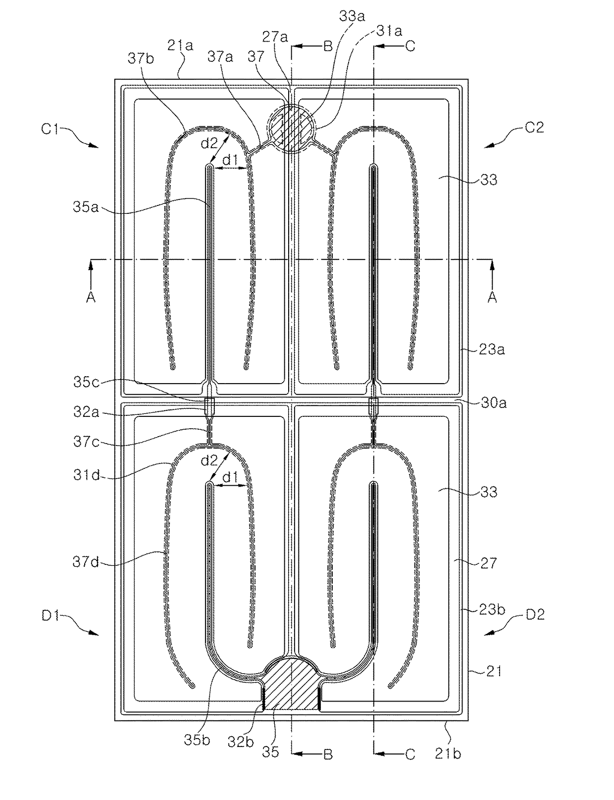
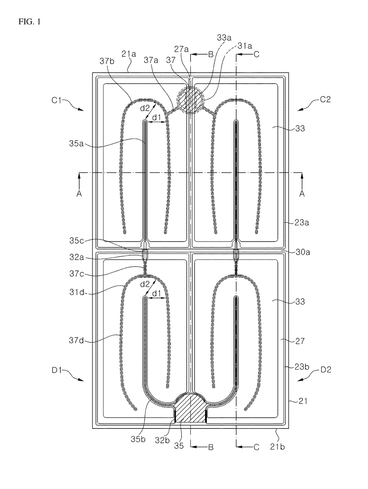
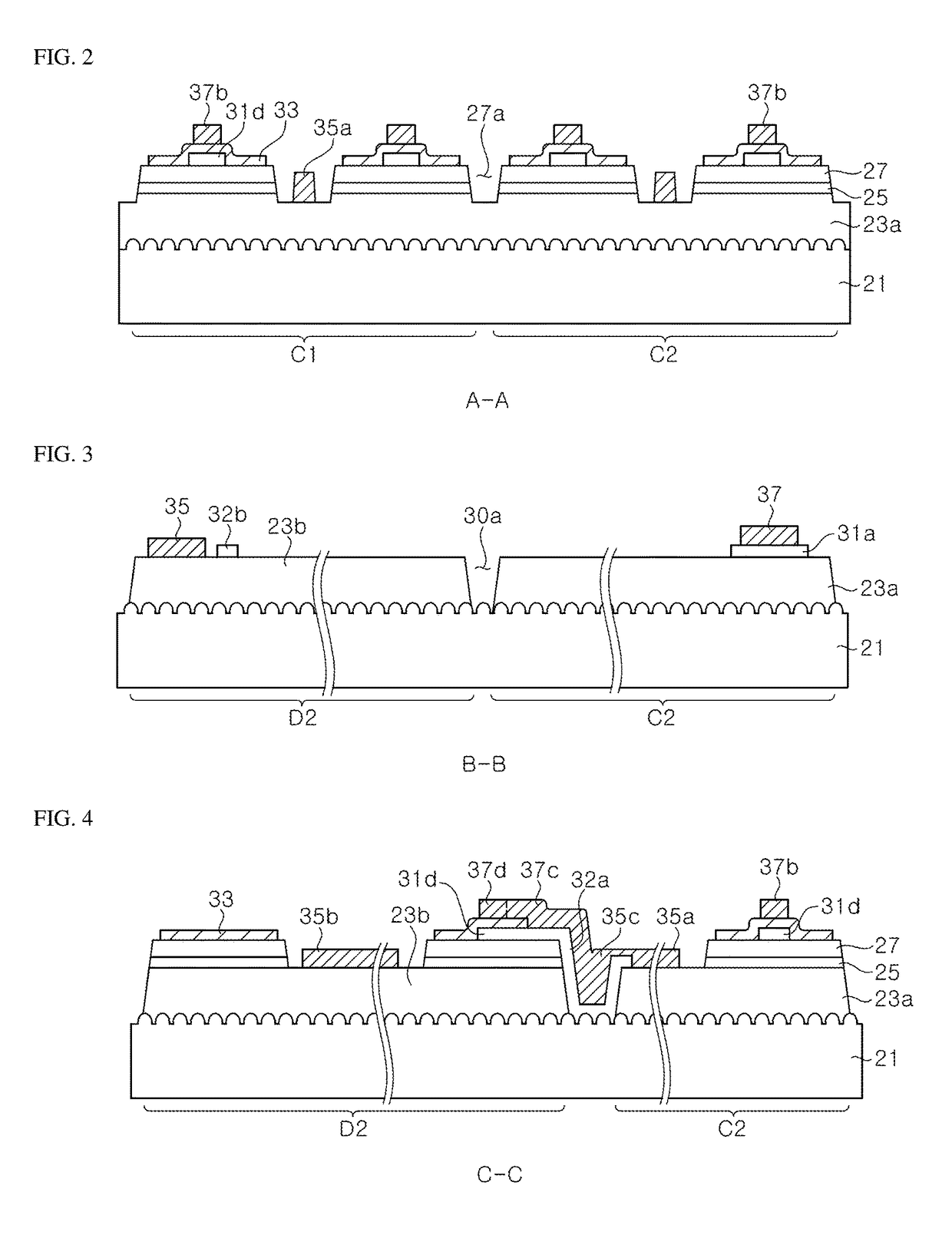
A light emitting diode includes: a substrate; a semiconductor stack disposed on the substrate and including a lower semiconductor layer, an upper semiconductor layer and an active layer interposed between the lower semiconductor layer and the upper semiconductor layer, the semiconductor stack having an isolation groove exposing the substrate through the upper semiconductor layer, the active layer and the lower semiconductor layer; a first electrode pad and an upper extension portion electrically connected to the upper semiconductor layer; a second electrode pad and a lower extension portion electrically connected to the lower semiconductor layer; a connecting portion connecting the upper extension portion and the lower extension portion to each other across the isolation groove; a first current blocking layer interposed between the lower extension portion and the lower semiconductor layer; and a second current blocking layer interposed between the second electrode pad and the lower semiconductor layer.

Description

CROSS-REFERENCE TO RELATED APPLICATION[0001]This application claims priority from and the benefit of Korean Patent Application No. 10-2016-0047054, filed on Apr. 18, 2016, Korean Patent Application No. 10-2016-0149627, filed on Nov. 10, 2016, and Korean Patent Application No. 10-2017-0020233, filed on Feb. 14, 2017, all of which are incorporated by reference for all purposes as if fully set forth herein.BACKGROUNDField[0002]Exemplary embodiments of the present disclosure relate to a light emitting diode, and more particularly, to a light emitting diode with high luminous efficacy.Discussion of the Background[0003]A light emitting diode (LED) refers to a solid state light emitting device that converts electrical energy into light. Light emitting diodes are broadly used as light sources for backlight units, lighting apparatus, traffic signals, large displays, and the like. With increasing demand for LEDs for lighting and expansion of application range to high current density and high ...

Claims


Application Information

Patent Timeline
IPC IPC(8): H01L33/14H01L33/42H01L33/32H01L33/10H01L33/06H01L33/62H01L27/15
CPCH01L33/145H01L33/06H01L33/32H01L27/15H01L33/42H01L33/62H01L33/10H01L33/36H01L33/38H01L2224/48091H01L2224/48137H01L27/156H01L2924/00014
Inventor LEE, KEUM JULEE, SEOM GEUNKIM, KYOUNG WANRYU, YONG WOOJANG, MI NA
Owner SEOUL VIOSYS CO LTD
Features
  • Generate Ideas
  • Intellectual Property
  • Life Sciences
  • Materials
  • Tech Scout
  • Unparalleled Data Quality
  • Higher Quality Content
  • 60% Fewer Hallucinations
Learn More