
Power supply arrangement

a power supply arrangement and power supply technology, applied in the direction of ac network circuit arrangement, dc-ac conversion without reversal, wind energy generation, etc., can solve the problems of power supply arrangement that requires safety precautions, the power supply may not meet the load requirements, and the possibility of uninterrupted power supply to a load, etc., to increase the safety of the power supply, increase the current load rating, and increase the effect of inrush curren

Active Publication Date: 2017-10-19
DELTA ELECTRONICS (THAILAND) PUBLIC CO LTD
View PDF7 Cites 7 Cited by
  • Summary
  • Abstract
  • Description
  • Claims
  • Application Information

AI Technical Summary

Benefits of technology

This patent describes a system that allows for automatic switching of a switching block, which is a type of electrical connector. The system is controlled by a controller, which makes the switching process easier and safer than manual switching. The system includes a protection switch, which is a type of contactor or a relay switch. The protection switch has two switching states and is designed to handle high current loadings. The use of a protection switch increases the robustness of the entire system. Overall, this patent provides a convenient and safe power supply arrangement.

Problems solved by technology

This opens the possibility of an uninterrupted power supply to a load even in case of a failure of one power source.
The output power of renewable power sources may vary over time and the produced output power may therefore not meet the requirements of the load at any time.
Furthermore, power supply arrangements require safety precautions.
Such an islanding may be dangerous to power grid workers, who may not realize that a circuit is still powered.
This is not convenient and causes the risk the bypass switch being at a wrong or at a disadvantageous switching position.
But not only the grid can fail but also the local power source may have a malfunction.
Systems known in the art do insufficiently consider that fact and have only a manual switches for example a bypass switch as descripted above for disconnecting the load from the power source.
Such manually operate bypass switch bear the risk of being at a wrong or at a disadvantageous switching position.
If a fault occurs in the power source or if the grid is not present and if the manually switched bypass is in a wrong position it may damage the concerned devices or it may even place persons at risk.
If the bypass switch is at a disadvantageous switching position the power source may feed power into the grid and the load is supplied with power from the grid.
That means the produced power may not be used for supplying the load which is disadvantageous from an economic point of view.

Method used


Image

  • Power supply arrangement
  • Power supply arrangement
  • Power supply arrangement

Examples


Embodiment Construction

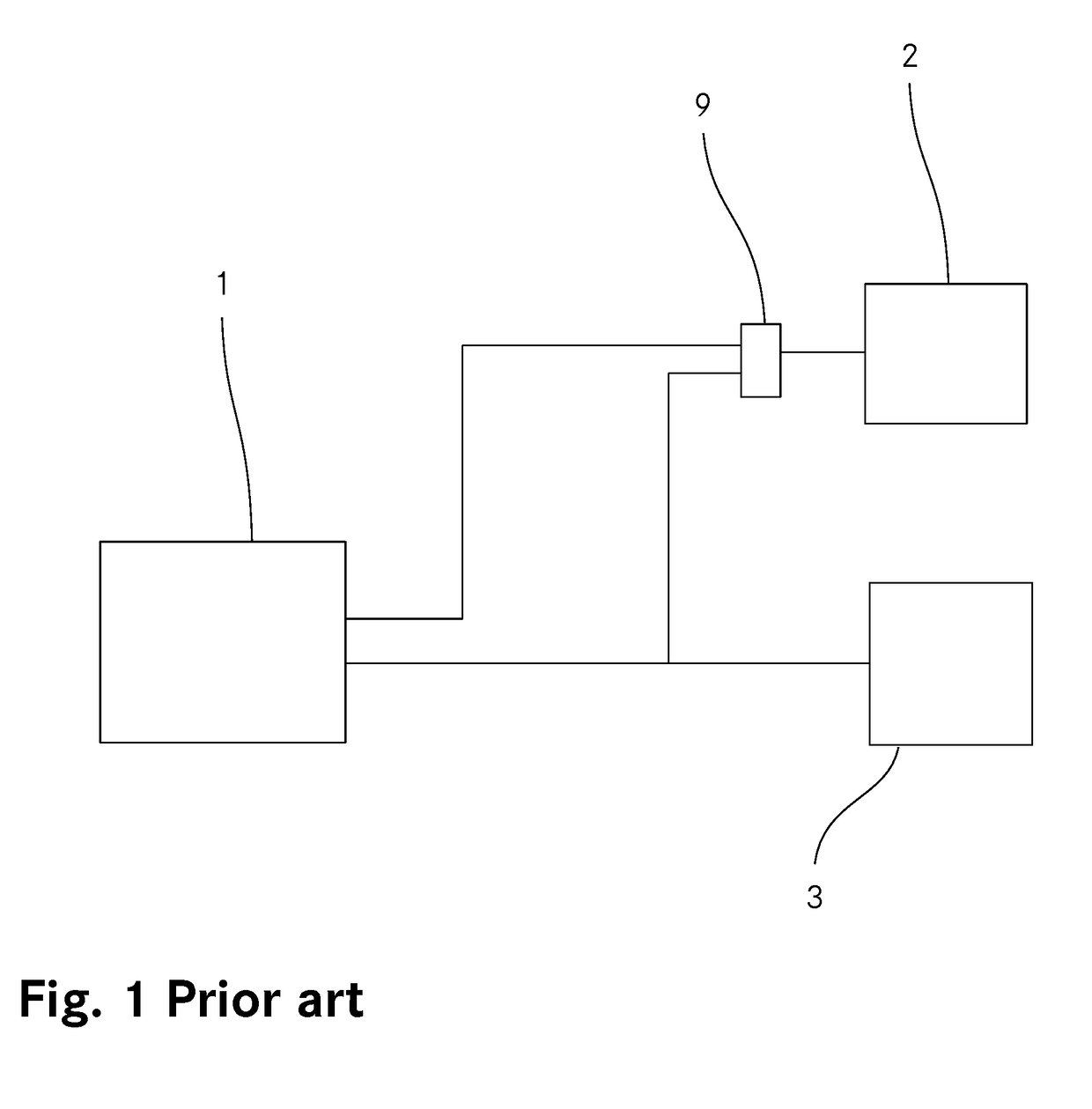
[0072]FIG. 1 shows a schematic circuit diagram of a power supply arrangement used for a domestic installation as it is known in the art. The power supply arrangement comprises a PV system 1 as a power source, an electrical load 2, a public power grid 3, and a mechanical bypass switch 9 having two switching states. In the first switching state of the bypass switch 9 the load 2 is connected to the PV system 1 and in the second switching state the load 2 is connected to the grid 3. The PV system 1 is optionally connected to the load 2 or to the grid 3 or to both, to the load 2 and to the grid 3.

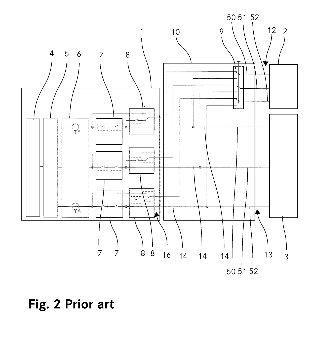
[0073]FIG. 2 shows a more detailed schematic circuit diagram of a power supply arrangement known in the art. As shown in FIG. 2 the power supply arrangement comprises a source interface 16 for connecting the PV system 1, a load interface 12 for connecting the load 2, a grid interface 13 for connecting the grid 3. The load 2 is connected through its load interface 12 to the source interface 16 of...


PUM


Abstract

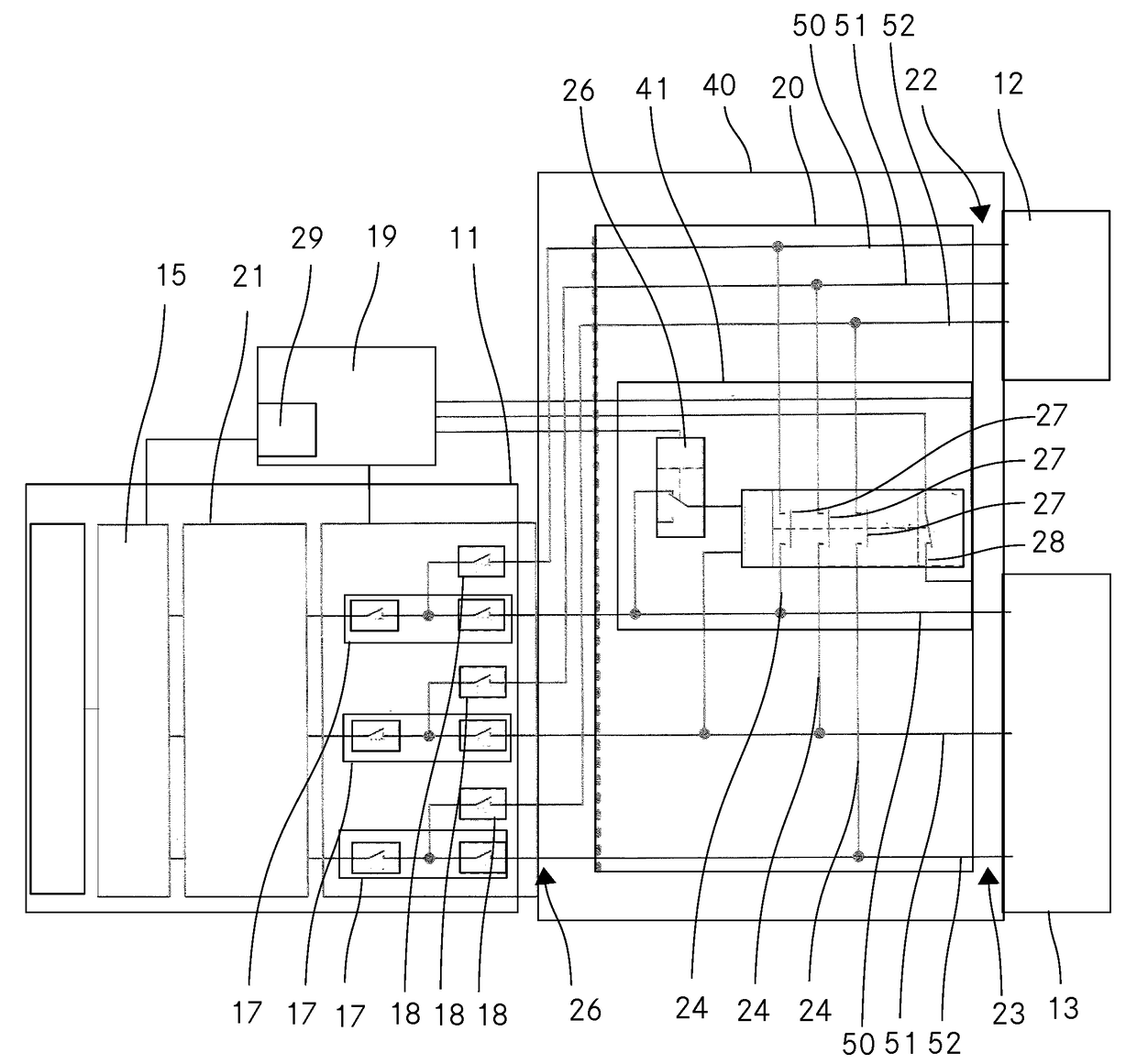
The present application relates to a power supply arrangement comprising a power source and a switching arrangement. The switching arrangement includes a switching block, wherein the switching block includes a source interface for connecting the power source, a load interface for connecting a load and a grid interface for connecting a power grid. The switching arrangement includes further a controller for controlling the switching block in dependency of the condition of the power source. The switching arrangement is implemented as a unit separate from the power source. The power supply arrangement comprises further a monitoring device for monitoring the condition of the power source.

Description

TECHNICAL FIELD[0001]The invention relates to a power supply arrangement comprising a power source and a switching arrangement. The switching arrangement comprises a switching block, wherein the switching block includes a source interface for connecting the power, a load interface for connecting a load and a grid interface for connecting a grid.BACKGROUND ART[0002]Access to electricity is of fundamental importance today. Power sources shall provide power at any times without interruption. This not only applies to large power plants supplying a region or a settlement area but also to local power source providing power for example to a premises. In the interests of ensuring an uninterrupted power supply electrical loads are often connected to more than one power source. This opens the possibility of an uninterrupted power supply to a load even in case of a failure of one power source.[0003]That does apply in particular to power supply arrangements comprising a renewable power source. ...

Claims


Application Information

Patent Timeline
Patent Type & Authority Applications(United States)
IPC IPC(8): H02J3/38H02M7/44
CPCH02J3/382H02M7/44H02J3/386H02J3/383H02J3/388H02J3/381H02J2300/24Y02E10/56Y02E10/76H02J3/38
Inventor WALLISER, DIETMARMENTELE, MICHAELSCHWEIZER, JURGEN
Owner DELTA ELECTRONICS (THAILAND) PUBLIC CO LTD
Learn More