

Dual passband radio frequency filter and communications device
a radio frequency filter and dual-passband technology, applied in the field of radio frequency filters, can solve the problems of communication dropout, phase shift or time delay, destructive interference with one another at the receiving antenna,
- Summary
- Abstract
- Description
- Claims
- Application Information
AI Technical Summary
Benefits of technology
Problems solved by technology
Method used
Image

Examples
example 1
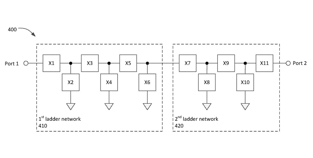
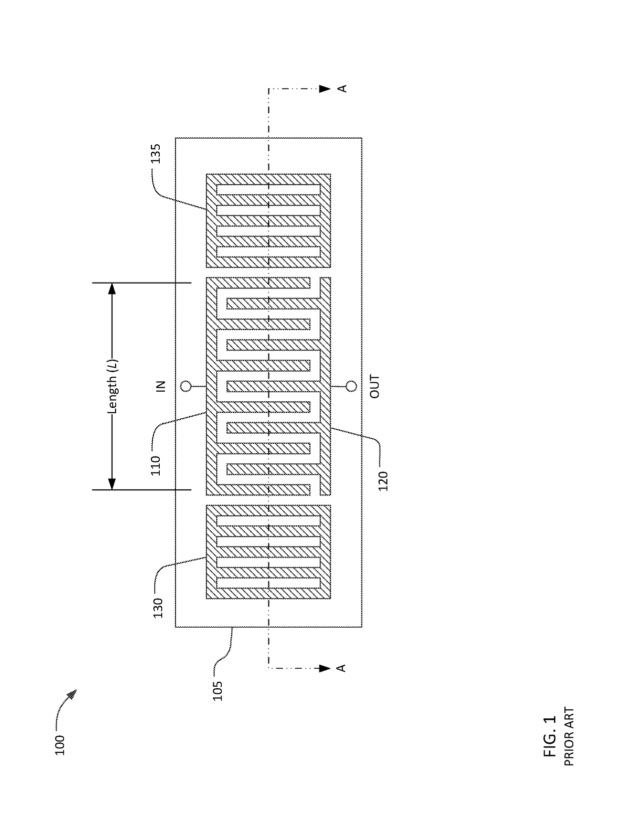
[0044]FIG. 6 shows a schematic diagram of band 2 / band 4 dual band-pass filter 600 including a first ladder network 610 in series with a second ladder network 620. The filter 600 has a lower pass-band and an upper pass-band separated by an intervening stop band. The lower pass-band accommodates the LTE band 2 receive band from 1930 to 1990 MHz. The upper pass-band accommodates the LTE band 4 receive band from 2110 to 2155 MHz. LTE bands 2 and 4 are widely used for cellular communications in North and South America, but are merely exemplary of relevant bands. The system may be applied to different frequency bands with similar effect. In FIG. 6, the first ladder network 610 includes four shunt resonators X1, X3, X5, X7, and four series resonators X2, X4, X6, X8. The second ladder network includes three shunt resonators X9, X11, X13, and two series resonators X10, X12. Each of the thirteen resonators X1-X13 may be comprised of inter-digital transducers and grating reflectors as shown in...
example 2
[0048]FIG. 8 shows a schematic diagram of band 1 / band 3 dual band-pass filter 800 including a first ladder network 810 in series with a second ladder network 820. The filter 800 has a lower pass-band and an upper pass-band separated by an intervening stop band. The lower pass-band accommodates the LTE band 3 receive band from 1805 to 1880 MHz. The upper pass-band accommodates the LTE band 1 receive band from 2110 to 2170 MHz. LTE bands 1 and 3 are widely used for cellular communications in Asia and Europe. The first ladder network 810 includes five series resonators X1, X3, X5, X7, X9 and four shunt resonators X2, X4, X6, X8. The second ladder network includes three shunt resonators X10, X12, X15, and three series resonators X11, X13, X15. Each of the fifteen resonators X1-X15 may be comprised of inter-digital transducers and grating reflectors as shown in FIG. 1. The motional resonance frequency Fr and the static capacitance C0 is provided for each resonator.
[0049]FIG. 9 is a graph...
example 3
[0052]FIG. 10 shows a schematic diagram of an exemplary three-band filter 1000 including a first ladder network 1010 and a second ladder network 1020 in series between an input port (Port 1) and an output port (Port 2). The first ladder network 1010 includes three series resonators X1, X3, X5 and three shunt resonators X2, X4, X6. The second ladder network 1020 includes four series resonators X7, X9, X11, X13 and four shunt resonators X8, X10, X12, X14. Each of the fourteen resonators X1-X14 may be comprised of inter-digital transducers and grating reflectors as shown in FIG. 1. The motional resonance frequency Fr and the static capacitance C0 is provided for each resonator.
[0053]FIG. 11 is a graph 1100 of the S(2,1) parameter of the three-band filter 1000. The solid line 1010 is a plot of S(2,1), which is the voltage transfer function from port 1 to port 2 of the three-band filter 1000. The filter 1000 has a lower pass-band, a middle pass-band, and an upper pass-band separated by l...
PUM
 Abstract
Description
Claims
Application Information