
Color light generating assembly, projection apparatus using the same and projection method thereof

Inactive Publication Date: 2017-10-19
QISDA OPTRONICS (SUZHOU) CO LTD +1
View PDF0 Cites 0 Cited by
  • Summary
  • Abstract
  • Description
  • Claims
  • Application Information

AI Technical Summary

Benefits of technology

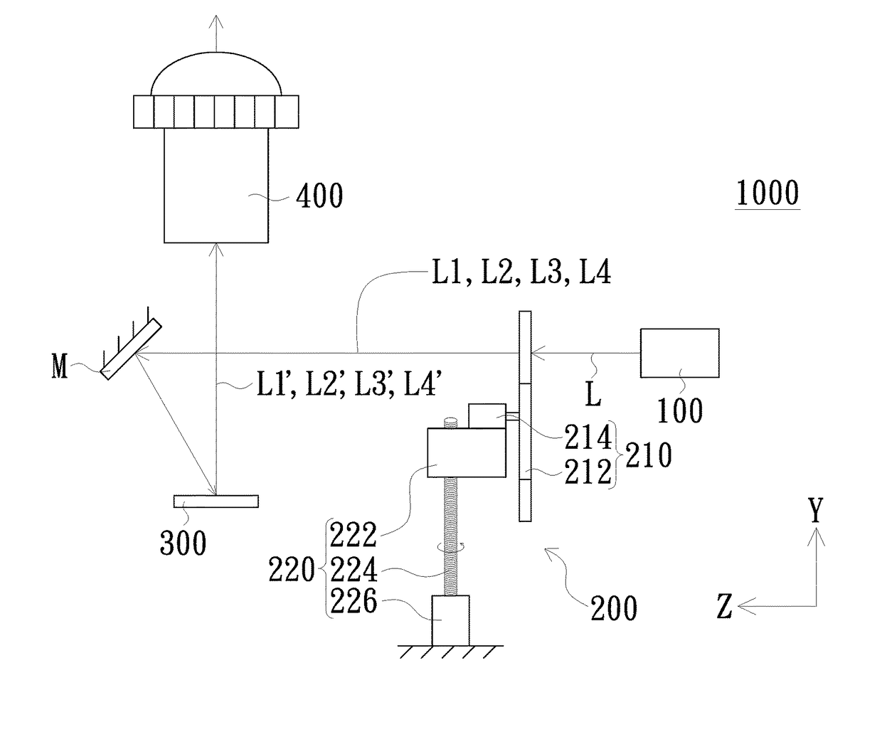
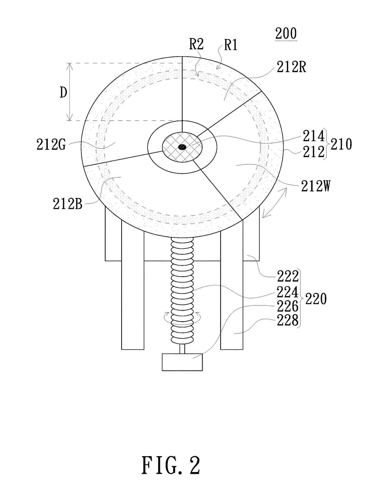
This patent aims to provide a color light generating assembly for a projection apparatus that can reduce the energy density of the illumination beam on the color wheel and avoid heat-induced deterioration. The assembly allows the color wheel to move in a different direction than the illumination beam, resulting in a more uniform distribution of energy on the wheel and a reduction in energy density per unit area. This enhances the stability and lifespan of the color wheel. The invention has practical applications in the field of projection technology.

Problems solved by technology

As a result, energy of the illumination beam is concentrated and distributed within the annular region; and consequently, heat in the annular region may rise dramatically and adversely impacts on the phosphor layer of the color wheel.

Method used


Image

  • Color light generating assembly, projection apparatus using the same and projection method thereof
  • Color light generating assembly, projection apparatus using the same and projection method thereof
  • Color light generating assembly, projection apparatus using the same and projection method thereof

Examples


Embodiment Construction

[0029]The present invention will now be described more specifically with reference to the following embodiments. It is to be noted that the following descriptions of preferred embodiments of this invention are presented herein for purpose of illustration and description only. It is not intended to be exhaustive or to be limited to the precise form disclosed.

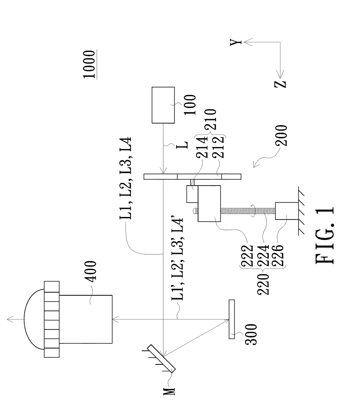
[0030]Please refer to FIG. 1, which is a schematic view of a projection apparatus in accordance with an embodiment of the present invention. As shown, the projection apparatus 1000 of the present embodiment includes a light source 100, a color light generating assembly 200, a light valve 300 and a projection lens 400. The light source 100 is configured to generate an illumination beam L. The illumination beam L is transmitted along a transmission path and irradiated onto the color light generating assembly 200. The color light generating assembly 200 is configured to sequentially convert the incident illumination beam L into a pl...


PUM


Abstract

A color light generating assembly includes a color wheel module and a reciprocating module. The color wheel module includes a color wheel and a first driving device. The color wheel is disposed on a transmission path of an illumination beam of the projection apparatus. An optical axis of the illumination beam irradiates the color wheel along a predetermined direction. The first driving device is configured to drive the color wheel to rotate so as to sequentially convert the illumination beam into a plurality of sub-illumination beams of different colors. The reciprocating module is connected to the color wheel module and configured to drive the color wheel module to reciprocate along a predetermined path when the color wheel is being driven to rotate by the first driving device. The predetermined direction is non-parallel to the predetermined path. A projection apparatus using the assembly and a projection method are also provided.

Description

FIELD OF THE INVENTION[0001]The present invention relates to a display device, and more particularly to projection apparatus, color light generating assembly and projecting method.BACKGROUND OF THE INVENTION[0002]Conventional projection apparatuses, especially digital light processing (DLP) projection apparatuses, employ color wheels to provide RGB colors for projection. Conventionally, color wheels employing fluorescent agents include a plurality of color light generating sheets. The color light generating sheets are coated with different fluorescent agents to form a plurality of phosphor layers with different colors. Therefore, lights with different colors are generated after the phosphor layers are sequentially irradiated by an illumination beam.[0003]In response to an increasing market demand for projection apparatuses with high brightness, projection apparatuses have been developed to generate high power beams to obtain high projection brightness. Consequently, color wheels in ...

Claims


Application Information

Patent Timeline
IPC IPC(8): H04N9/31G03B21/16G02B26/00
CPCH04N9/3114G03B21/16G02B26/008G03B21/204
Inventor LIN, CHI-CHENG
Owner QISDA OPTRONICS (SUZHOU) CO LTD
Learn More