Liquid crystal display device

a liquid crystal display and display device technology, applied in non-linear optics, instruments, optics, etc., can solve problems such as worsening of parallax color mixtures, and achieve the effects of reducing the reflection of outside light, reducing the worsening of parallax color mixtures, and good outside visibility

Active Publication Date: 2021-02-23
SHARP KK
View PDF2 Cites 0 Cited by
  • Summary
  • Abstract
  • Description
  • Claims
  • Application Information

AI Technical Summary

Benefits of technology

[0008]In response to the above issues, the present invention aims to provide a liquid crystal display device capable of reducing reflection of outside light, of achieving good outside visibility, and of reducing worsening of parallax color mixture.
[0014]The present invention can provide a liquid crystal display device capable of reducing reflection of outside light, of achieving good outside visibility, and of reducing worsening of parallax color mixture.

Problems solved by technology

This disadvantageously causes worsening of parallax color mixture.

Method used


Image

  • Liquid crystal display device
  • Liquid crystal display device
  • Liquid crystal display device

Examples


embodiment 1

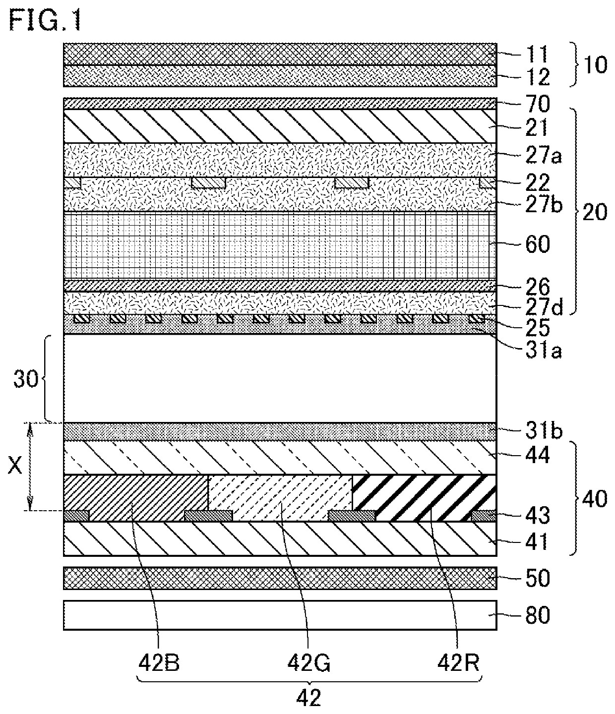
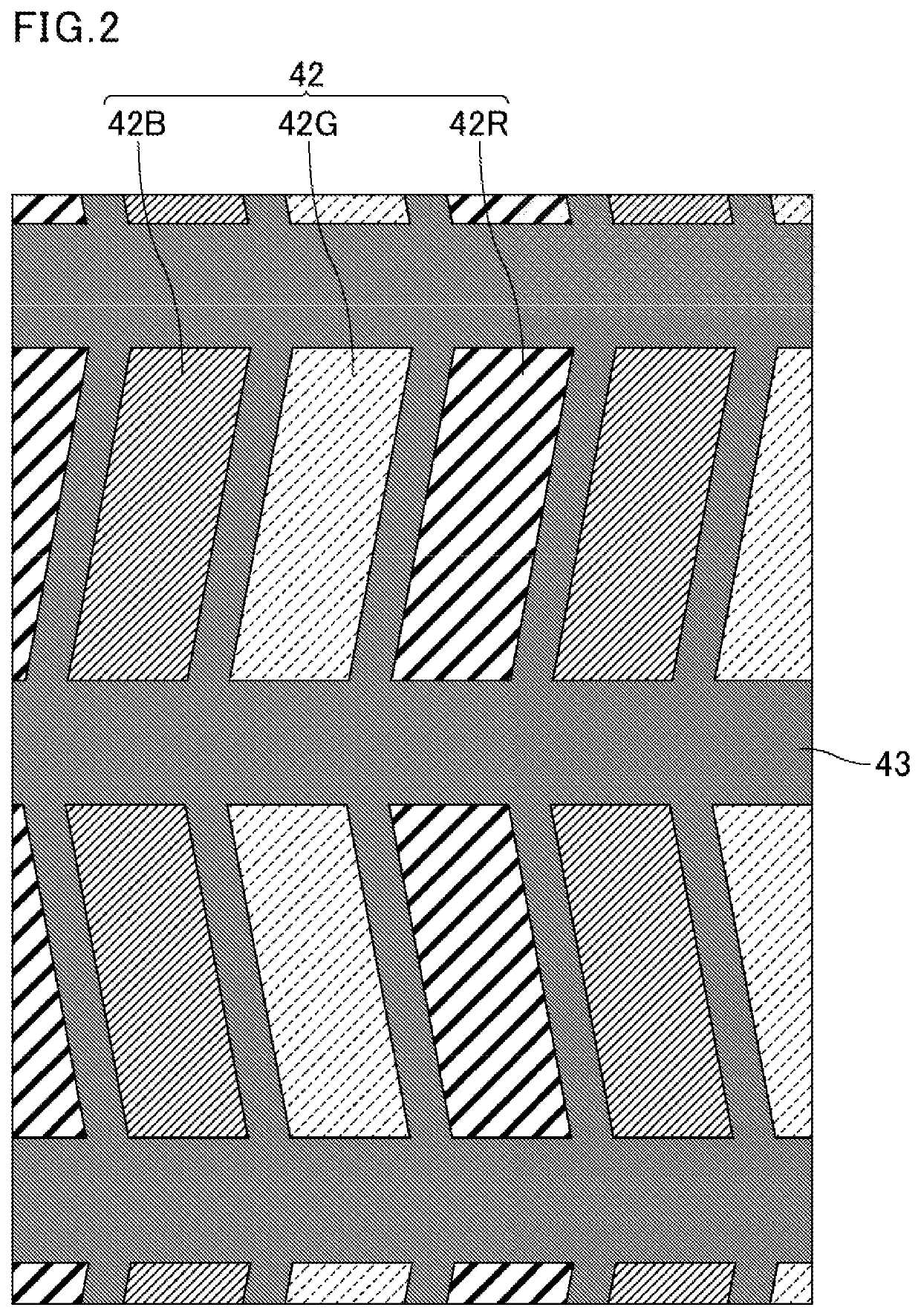
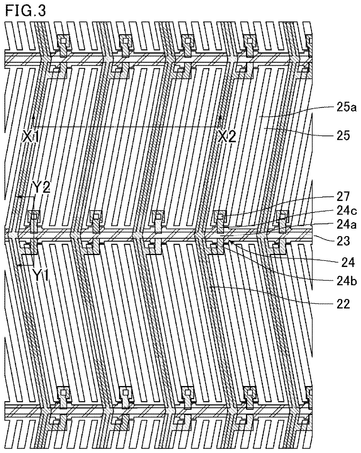
[0045]FIG. 1 is a schematic cross-sectional view of a structure of a liquid crystal display device of Embodiment 1. FIG. 2 is a schematic plan view of a color filter substrate of the liquid crystal display device of Embodiment 1. FIG. 3 is a schematic plan view of a TFT substrate of the liquid crystal display device of Embodiment 1. FIG. 4 is a schematic cross-sectional view of the TFT substrate of the liquid crystal display device of Embodiment 1, illustrating a TFT portion. FIG. 1 corresponds to the cross section taken along the X1-X2 line in FIG. 3. FIG. 4 corresponds to the cross section taken along the Y1-Y2 line in FIG. 3. The liquid crystal display device of the present embodiment is an FFS mode liquid crystal display device (low reflective LCD) including a circularly polarizing plate. As illustrated in FIG. 1, the liquid crystal display device includes a liquid crystal panel that sequentially includes, from the viewing side, the circularly polarizing plate 10, a thin-film tr...

example 1

[0079]With the structure of Embodiment 1, the chromaticity (u′, v′) was calculated using LCD Master when the panel displaying a single color selected from blue, green, red was observed from the front and from an angle (polar angle of 60° and an azimuth angle of 0° or 180°). FIG. 7 is a cross-sectional view of a structure of a liquid crystal display device of Example 1 used for calculation. The 2D model illustrated in FIG. 7 was used for calculation.

[0080]In the examples and the comparative examples, the azimuth angle 0° and the azimuth angle 180° are respectively defined as the direction of observing the panel from the right of the sheet and the left of the paper in the figure of the cross-sectional structure used for calculation.

[0081]The thickness of the in-cell retarder 60 was set to 1.0 μm, 2.0 μm, or 3.0 μm. The thickness of the interlayer insulating film 27d was set to 0.2 μm. The line (L) / space (S) ratio of each pixel electrode 25 was set to 2.2 μm / 3.2 μm. The thickness of th...

embodiment 2

[0087]In the present embodiment, the features unique to the present embodiment are mainly described and the descriptions of the same contents as for Embodiment 1 are omitted as appropriate. In the present description, the components having the same or similar function have the same reference sign, and the same descriptions of these components are omitted.

[0088]FIG. 11 is a schematic cross-sectional view of a structure of a liquid crystal display device of Embodiment 2. FIG. 12 is a schematic cross-sectional view of a TFT substrate of the liquid crystal display device of Embodiment 2, illustrating a TFT portion. FIG. 11 corresponds to the cross section taken along the X1-X2 line in FIG. 3. FIG. 12 corresponds to the cross section taken along the Y1-Y2 line in FIG. 3. The liquid crystal display device of the present embodiment is an FFS mode liquid crystal display device (low reflective LCD) including a circularly polarizing plate. As illustrated in FIG. 11, the liquid crystal display...


PUM

PropertyMeasurementUnit
wavelengthaaaaaaaaaa

Abstract

A liquid crystal display device includes a liquid crystal panel and a circularly polarizing plate disposed on a viewing side of the liquid crystal panel. The circularly polarizing plate sequentially includes, from a viewing side, a linearly polarizing plate and an out-cell retarder. The liquid crystal panel includes a thin-film transistor substrate, a color filter substrate facing the thin-film transistor substrate and including black matrix, a horizontal alignment liquid crystal layer disposed between the thin-film transistor substrate and the color filter substrate, and an in-cell retarder disposed in one substrate disposed on the viewing side selected from the thin-film transistor substrate and the color filter substrate. The in-cell retarder is disposed outside a region between the black matrix and the horizontal alignment liquid crystal layer.

Description

CROSS-REFERENCE TO RELATED APPLICATIONS[0001]The present application claims priority under 35 U.S.C. § 119 to Japanese Patent Application No. 2018-214682 filed on Nov. 15, 2018, the contents of which are incorporated herein by reference in their entirety.BACKGROUND OF THE INVENTIONField of the Invention[0002]The present invention relates to liquid crystal display devices.Description of Related Art[0003]Liquid crystal display devices utilize a liquid crystal composition for display. In a typical display mode, a liquid crystal panel containing a liquid crystal composition between paired substrates is irradiated with light from a backlight while voltage is applied to the liquid crystal composition to change the alignment of liquid crystal molecules, whereby the amount of light passing through the liquid crystal panel is controlled. Such liquid crystal display devices have advantageous features such as thin profile, light weight, and low power consumption, and are therefore used in elec...

Claims


Application Information

Patent Timeline
Patent Type & Authority Patents(United States)
IPC IPC(8): G02F1/1335G02F1/1337
CPCG02F1/133514G02F1/1337G02F1/133512G02F1/133528G02F2201/121G02F2201/123G02F1/13363G02F1/1368G02F1/136209G02F1/136286G02F2413/02G02F1/134363G02F2413/06G02F1/133555G02F2413/04G02F1/133541G02F1/133638G02F1/134372G02F1/133502G02F1/133565
Inventor KAWAHIRA, YUICHIKOIDE, TAKAKOSAKAI, AKIRAMINOURA, KIYOSHI
Owner SHARP KK
Why Eureka
Try Eureka