
Alternately direct resistance spot welding of al-to-al, al-to-steel, and steel-t0-steel with welding electrode having oxide-disrupting structural features

a technology of resistance spot welding and steel-t0-steel, which is applied in the direction of resistance electrode holders, electrode maintenance, manufacturing tools, etc., can solve the problems of workpiece stacking, and neither of those practices is particularly attractiv

Active Publication Date: 2017-10-26
GM GLOBAL TECH OPERATIONS LLC
View PDF3 Cites 18 Cited by
  • Summary
  • Abstract
  • Description
  • Claims
  • Application Information

AI Technical Summary

Benefits of technology

The patent describes a method of resistance spot welding workpiece stack-ups of different combinations of metal workpieces using a single weld gun. The method involves restoring the weld faces of the opposed welding electrodes by inserting them into a cutting tool and rotating it to shear away material from the weld faces. The resulting weld faces have a smooth surface texture and can be further textured to create a microtexture. The method can be used with aluminum and steel workpieces, and can also include forming aluminum-to-aluminum and steel-to-steel spot welds before and after restoring the weld faces. The technical effects of the method include improved weld quality and efficiency in resistance spot welding workpiece stack-ups.

Problems solved by technology

Such strategic use of these metals invariably results in workpiece stack-ups that present a variety of lapped metal workpiece combinations.
But spot welding the various combinations of metal workpieces that may be presented in a workpiece stack-up poses certain challenges.
Neither of those practices is particularly attractive solution.

Method used


Image

  • Alternately direct resistance spot welding of al-to-al, al-to-steel, and steel-t0-steel with welding electrode having oxide-disrupting structural features
  • Alternately direct resistance spot welding of al-to-al, al-to-steel, and steel-t0-steel with welding electrode having oxide-disrupting structural features
  • Alternately direct resistance spot welding of al-to-al, al-to-steel, and steel-t0-steel with welding electrode having oxide-disrupting structural features

Examples


Embodiment Construction

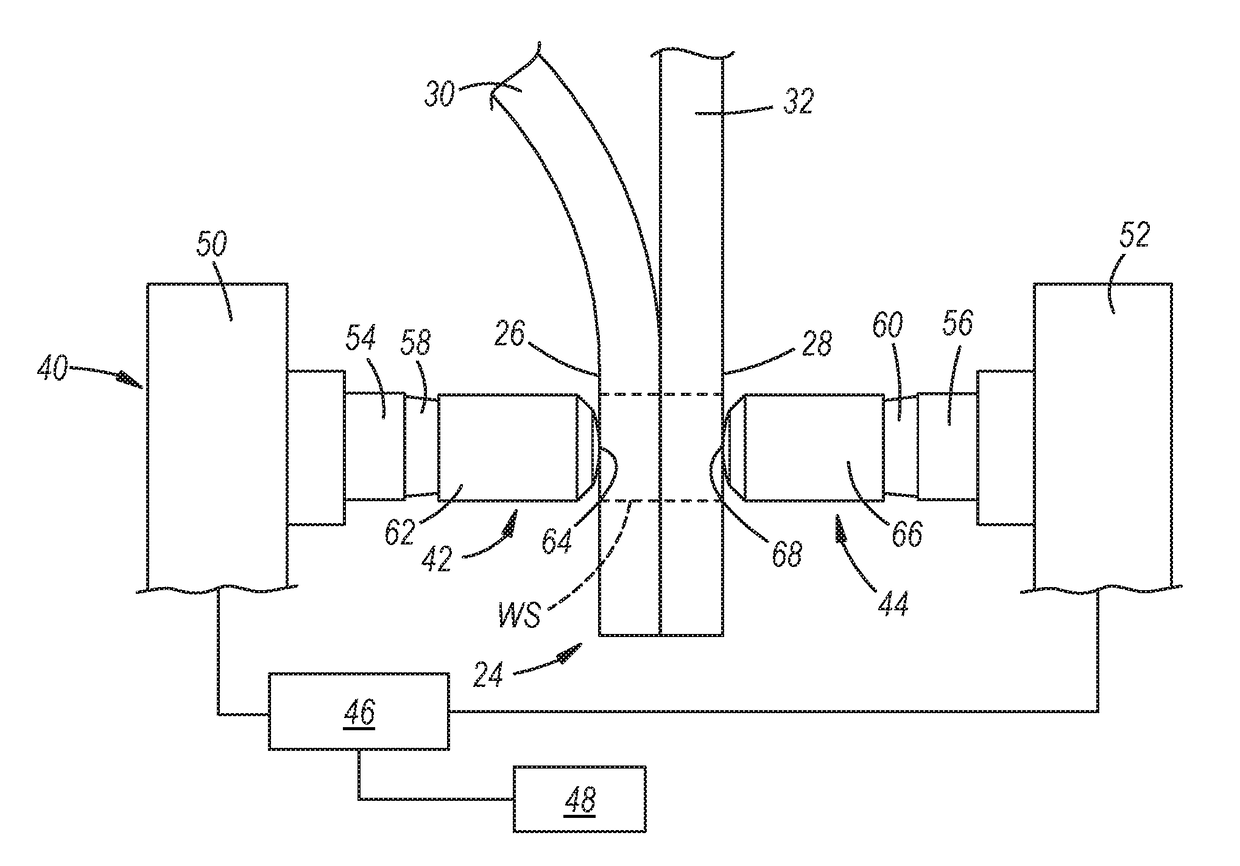
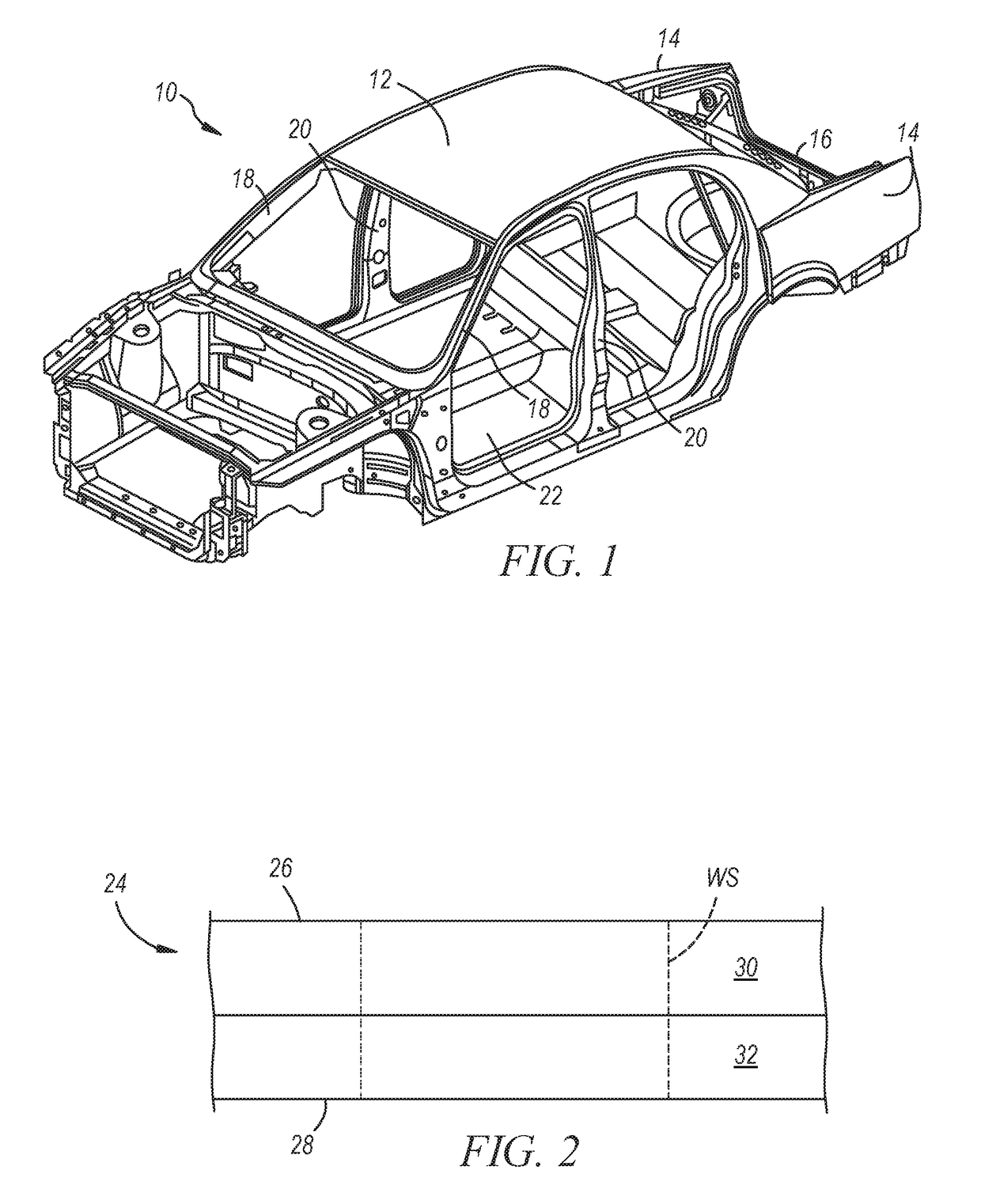
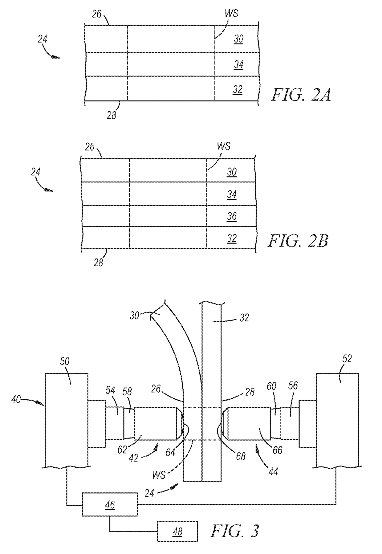
[0035]A method is disclosed that enables workpiece stack-ups of different combinations of metal workpieces to be resistance spot welded with a single weld gun using the same set of welding electrodes. The different combinations of metal workpieces that comprise the workpiece stack-ups where spot welding is practiced fall in to three categories: (1) a workpiece stack-up of two or more aluminum workpieces; (2) a workpiece stack-up that includes an aluminum workpiece and an adjacent steel workpiece along with one or more optional aluminum workpieces and / or one or more optional steel workpieces so long as all of the aluminum workpieces and all of the steel workpieces are disposed adjacent to each other; or (3) a workpiece stack-up of two or more steel workpieces. The terms “aluminum workpiece” and “steel workpiece” are used broadly in the present disclosure and encompass any resistance spot weldable form of aluminum and steel, respectively. Some preferred and specific examples of alumin...


PUM

PropertyMeasurementUnit
Raaaaaaaaaaa
thicknessaaaaaaaaaa
thicknessaaaaaaaaaa

Abstract

A method of resistance spot welding workpiece stack-ups of different combinations of metal workpieces with a single weld gun using the same set of welding electrodes is disclosed. In this method, a set of opposed welding electrodes that include an original shape and oxide-disrupting structural features are used to resistance spot weld at least two of the following types of workpiece stack-ups in a particular sequence: (1) a workpiece stack-up of two or more aluminum workpieces; (2) a workpiece stack-up that includes an aluminum workpiece and an adjacent steel workpiece; and (3) a workpiece stack-up of two or more steel workpieces. The spot welding sequence calls for completing all of the aluminum-to-aluminum spot welds and / or all of the steel-to-steel spot welds last.

Description

CROSS-REFERENCE TO RELATED APPLICATION(S)[0001]This application claims the benefit of U.S. Provisional Application Nos. 62 / 326,089 and 62 / 326,092, each of which was filed on Apr. 22, 2016. The entire contents of each of the aforementioned provisional applications are incorporated herein by reference.TECHNICAL FIELD[0002]The technical field of this disclosure relates generally to resistance spot welding and, more particularly, to a methodology of resistance spot welding workpiece stack-ups with different combinations of metal workpieces using a single weld gun and the same set of opposed welding electrodes.INTRODUCTION[0003]Resistance spot welding is a well-known joining technique that relies on the resistance to the flow of an electrical current through overlapping metal workpieces and across their faying interface(s) to generate the heat needed for welding. To carry out such a welding process, a set of opposed spot welding electrodes is clamped at aligned spots on opposite sides of...

Claims


Application Information

Patent Timeline
Patent Type & Authority Applications(United States)
IPC IPC(8): B23K11/31B23K11/20B23K11/11B23K11/30B23K11/24B23K103/04B23K103/10B23K103/20
CPCB23K11/315B23K11/20B23K11/24B23K2203/04B23K11/3063B23K2203/20B23K2203/10B23K11/115B23K11/185B23K11/3009B23K2101/006B23K2101/18B23K2103/20B23K2103/04B23K2103/10
Inventor SIGLER, DAVID R.CARLSON, BLAIR E.KARAGOULIS, MICHAEL J.
Owner GM GLOBAL TECH OPERATIONS LLC
Learn More