
Wheel suspension with centrally pivoted transverse leaf spring

a technology of transverse leaf spring and central pivot, which is applied in the direction of vehicle springs, transportation and packaging, trucks, etc., can solve the problems of reduced vehicle handling performance, high manufacturing and maintenance costs, and high maintenance costs of double wishbone suspension design, so as to improve longitudinal stability and reduce manufacturing costs. , the effect of high longitudinal for

Active Publication Date: 2017-10-26
VOLVO LASTVAGNAR AB
View PDF1 Cites 8 Cited by
  • Summary
  • Abstract
  • Description
  • Claims
  • Application Information

AI Technical Summary

Benefits of technology

The patent text is about a new design for a wheel suspension arrangement for vehicles that is simpler and less expensive to manufacture and maintain than existing designs. The design uses a single rigid control arm, which reduces manufacturing costs compared to multi-unit control arms. The technical effect of this design is improved vehicle handling and reduced manufacturing and maintenance costs.

Problems solved by technology

Each wheel suspension arrangement is associated with certain advantages and disadvantages in terms of manufacturing cost, weight, robustness, required maintenance cost, vehicle handling, tire wear, etc.
The double wishbone suspension design is however generally also conceived as having a relatively high manufacturing and maintenance cost due the high complexity of the linkage and elastic mountings.
The double wishbone design also has drawbacks in terms of varying wheel camber angle upon vehicle body roll, which typically occurs during vehicle cornering.
A varying camber angle is generally undesirable because this result in a camber angle that offset from a desired, optimal, camber angle during certain vehicle operating conditions.
Driving a vehicle with a camber angle offset from a desired camber angle generally results in reduced vehicle handling performance and in increased tire wear.
However, during vehicle cornering, a long term unsymmetrical force will act on the body roll damper unit such that the leaf spring will pivot around its pivotal connection for providing the desired camber compensation.

Method used


Image

  • Wheel suspension with centrally pivoted transverse leaf spring
  • Wheel suspension with centrally pivoted transverse leaf spring
  • Wheel suspension with centrally pivoted transverse leaf spring

Examples


Embodiment Construction

[0051]Various aspects of the invention will hereinafter be described in conjunction with the appended drawings to illustrate and not to limit the invention, wherein like designations denote like elements, and variations of the inventive aspects are not restricted to the specifically shown embodiments, but are applicable on other variations of the invention.

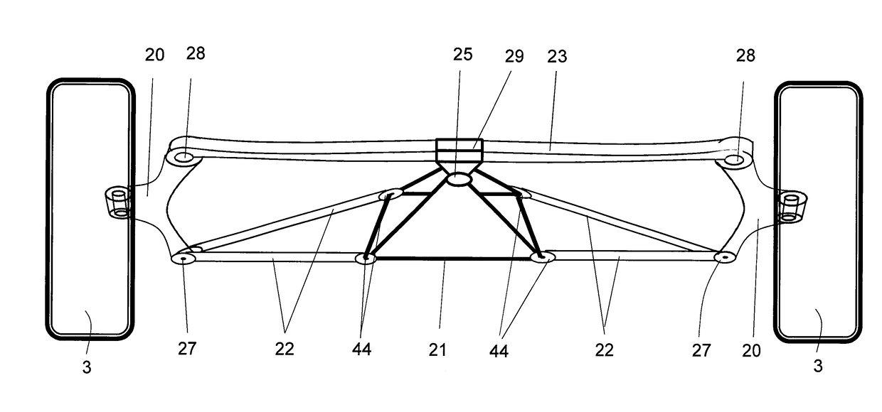
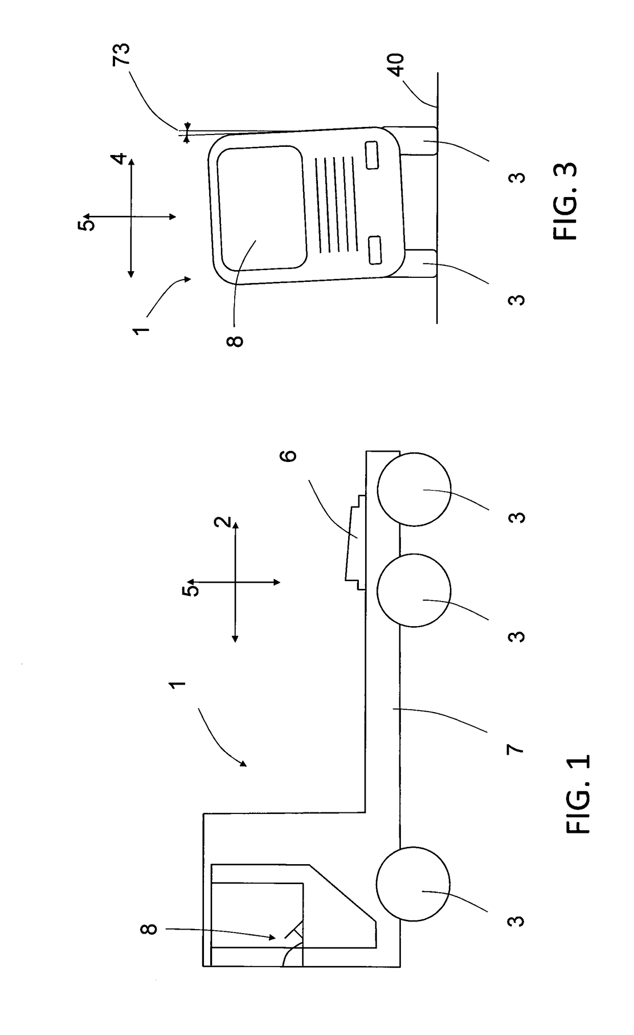
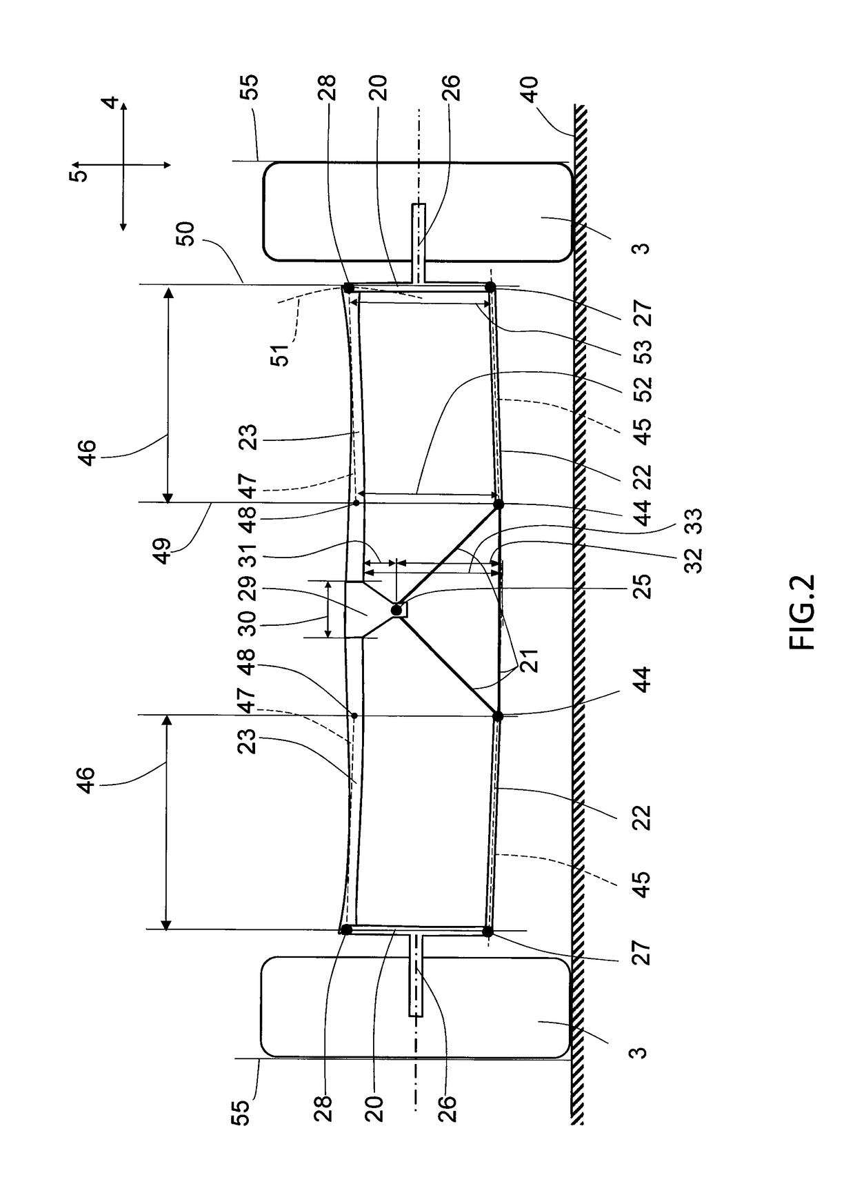
[0052]FIG. 1 illustrates schematically a vehicle 1 suitable for using a wheel suspension arrangement according to an aspect of the invention. The vehicle has a longitudinal direction 2, a transverse direction 4 and a vertical direction 5 and may be any type of road vehicle having wheel suspension arrangement, in particular heavy vehicles, such as trucks, buses, and constructional vehicles, but also automobiles or railbound vehicles. The vehicle 1 shown in FIG. 1 illustrates a heavy truck for being connected to a trailer via a fifth wheel 6. The truck further comprises a frame 7, a driver's cabin 8 and a pair of steerable front whe...


PUM


Abstract

A wheel suspension arrangement is provided for a vehicle having a longitudinal direction, a transverse direction and a vertical direction. The wheel suspension arrangement includes a wheel holder for supporting a vehicle wheel. A first vertical end region of the wheel holder is pivotally attached to a vehicle support structure by a rigid control arm and a second vertical end region of the wheel holder is attached to the vehicle support structure by a leaf spring. A longitudinal direction of the leaf spring is arranged substantially in the transverse direction of the vehicle. The leaf spring is pivotally attached to the vehicle support structure at a transverse centre region of the vehicle, and a centre of the leaf spring in the transverse direction is located vertically offset from a pivotal attachment location of the leaf spring. The pivotal attachment location of the leaf spring is vertically offset towards the side of the rigid control arm.

Description

BACKGROUND AND SUMMARY[0001]The invention relates to a wheel suspension arrangement for a vehicle having a longitudinal direction, a transverse direction and a vertical direction. The wheel suspension arrangement comprising a wheel holder for supporting a vehicle wheel, wherein a first vertical end region of the wheel holder is pivotally attached to a vehicle support structure by means of a rigid control arm, and wherein the second vertical end region of the wheel holder is attached to the vehicle support structure by means of a leaf spring. A longitudinal direction of the leaf spring is arranged substantially in the transverse direction of the vehicle. The leaf spring is pivotally attached to the vehicle support structure at a transverse centre region of the vehicle, and the leaf spring is located vertically offset from a pivotal attachment location of the leaf spring.[0002]The invention is suitable for being applied in heavy-duty vehicles, such as trucks and buses. Although the in...

Claims


Application Information

Patent Timeline
IPC IPC(8): B60G5/047
CPCB60G5/047B60G2204/121B60G2202/114B60G11/08B60G11/10B60G2300/02B60G2300/026B60G2300/14B60G3/28B60G11/34B60G13/005B60G2200/144B60G2200/46B60G2202/22B60G2204/13B60G2204/143B60G2204/82B60G2204/8302B60G2204/8306B60G2206/428
Inventor PREIJERT, STEFANYARMOHAMADI, HODA
Owner VOLVO LASTVAGNAR AB
Learn More