
Train Brake Control System And Method

Inactive Publication Date: 2017-10-26
WESTINGHOUSE AIR BRAKE TECH CORP
View PDF22 Cites 10 Cited by
  • Summary
  • Abstract
  • Description
  • Claims
  • Application Information

AI Technical Summary

Benefits of technology

This patent is about an improved system for controlling train brakes. The system can work better for multiple units of locos that use pneumatic brazing. It also takes into account the need to control brake pressure at different levels for different types of locos. This is important because the system uses communications-based demands, instead of pneumatic pressure. Overall, the system helps to make train braking more efficient and effective.

Problems solved by technology

Accordingly, one issue is that arises involves the multiplier functionality, which should typically only be applied to the independent braking portion of the demand.
In conventional ECP braking systems, the trailing locomotives are not equipped to determine the source of the control pipe demand, and may incorrectly apply the multiplier to demand that is present in the control pipe due to automatic braking demand.
This can result in over-braking or under-braking, depending on the implementation and the difference in the locomotive's multipliers.

Method used


Image

  • Train Brake Control System And Method
  • Train Brake Control System And Method
  • Train Brake Control System And Method

Examples


Embodiment Construction

[0064]For purposes of the description hereinafter, the terms “upper”, “lower”, “right”, “left”, “vertical”, “horizontal”, “top”, “bottom”, “lateral”, “longitudinal” and derivatives thereof shall relate to the invention as it is oriented in the drawing figures. It is to be understood that the invention may assume various alternative variations and step sequences, except where expressly specified to the contrary. It is also to be understood that the specific devices and processes illustrated in the attached drawings, and described in the following specification, are simply exemplary embodiments of the invention. Hence, specific dimensions and other physical characteristics related to the embodiments disclosed herein are not to be considered as limiting.

[0065]As used herein, the terms “communication” and “communicate” refer to the receipt, transmission, or transfer of one or more signals, messages, commands, or other type of data. For one unit or device to be in communication with anot...


PUM


Abstract

A brake control system and method for a train having a lead locomotive or control car, at least one trailing locomotive or control car and, optionally, at least one railroad car. The lead locomotive or control car generates data representing an independent brake demand and data representing an automatic brake demand and transmits the data representing an independent brake demand and the data representing an automatic brake demand to the at least one trailing locomotive or control car. The at least one trailing locomotive or control car receives data representing an independent brake demand and data representing an automatic brake demand and controls a brake cylinder pressure of the at least one trailing locomotive or control car based on the data representing an independent brake demand and the data representing an automatic brake demand.

Description

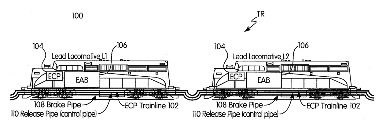
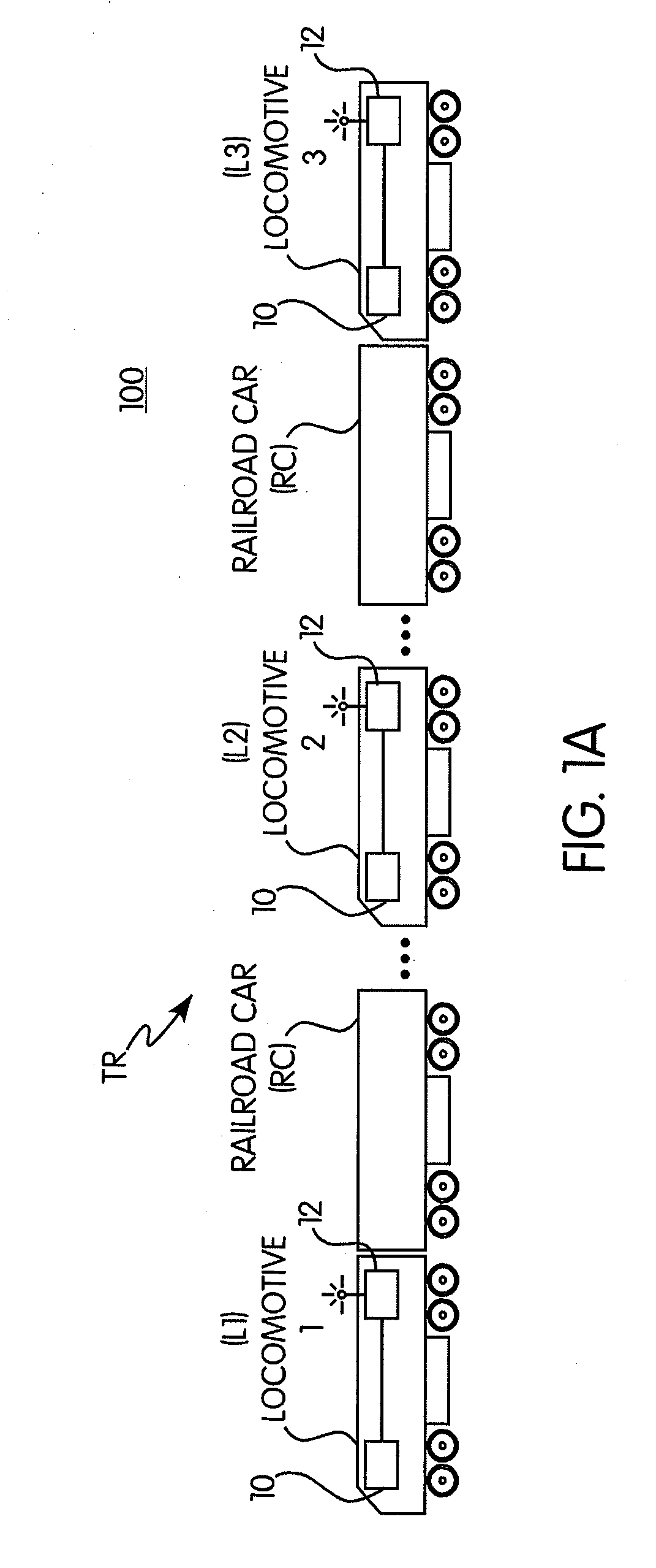
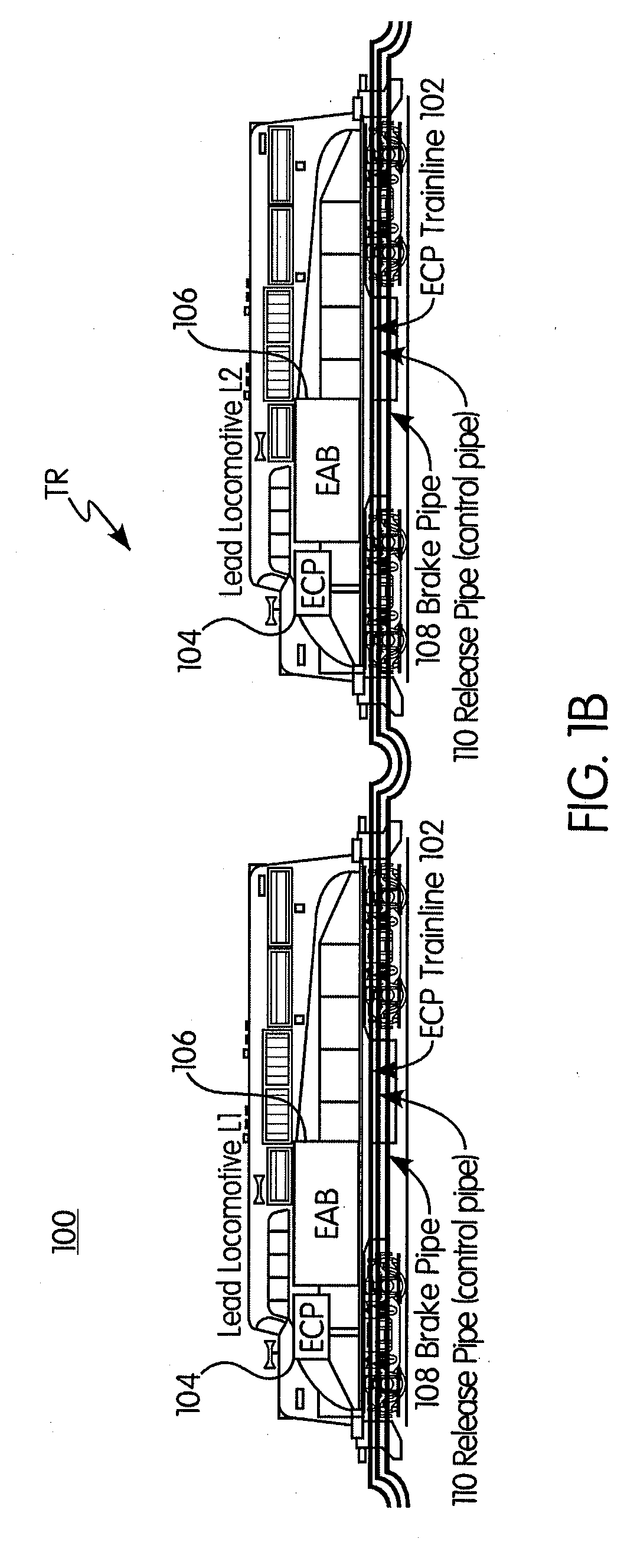
BACKGROUND OF THE INVENTIONField of the Invention[0001]Disclosed embodiments relate generally to vehicle systems and control processes, such as railway systems including trains travelling in a track or rail network, and in particular to a train brake control system and method that provide improved train brake control in railway networks, such as in connection with automatic electronically-controlled pneumatic (ECP) brake control.Description of Related Art[0002]As is known in the field of train control, and when operating a train having multiple locomotives or control cars, the lead and trailing locomotives are interconnected with various pneumatic pipes, including a “brake pipe” and an “independent apply and release pipe” also known as the “20-pipe” or “No. 3 Control Pipe”. These two pipes operate two separate brake systems when a train is operating in pneumatic mode, i.e., automatic or pneumatic braking via the brake pipe and independent braking via the control pipe.[0003]The brake...

Claims


Application Information

Patent Timeline
IPC IPC(8): B61L27/04B61H9/00B60T8/17B61H11/02B61H11/06B61H13/00
CPCB61L27/04B61H9/006B61H11/06B61L2201/00B61H11/02B60T8/1705B61H13/00B61L15/0027B61L15/0072B60T13/665B60T17/228B61L15/0062
Inventor KLEMANSKI, RICHARD S
Owner WESTINGHOUSE AIR BRAKE TECH CORP
Learn More