Supercharge Your Innovation With Domain-Expert AI Agents!

Micromechanical device having a decoupled micromechanical structure

a micromechanical structure and micromechanical technology, applied in the direction of fluid speed measurement, instruments, coatings, etc., can solve the problem of limiting the selection of packaging options in terms of form and material, and achieve the effects of less attention, better stability of sensor signals, and positive damping

Active Publication Date: 2017-10-26
ROBERT BOSCH GMBH
View PDF8 Cites 6 Cited by
  • Summary
  • Abstract
  • Description
  • Claims
  • Application Information

AI Technical Summary

Benefits of technology

The present invention is a micromechanical device that includes a fixed part and a mobile part, which are movably connected to each other with the aid of at least one spring element, and a first cavity that is situated in the mobile part. This allows for the mobile micromechanical structure to be mechanically decoupled and damped from its environment without the entire micromechanical device having to be decoupled and damped from its environment. The invention also provides different rigidities, locations, and geometries of the spring element. Additionally, the invention includes a method for producing the micromechanical device that allows for a mechanical decoupling of the mobile micromechanical structure from its environment and packaging at the wafer level as well as sealing from environmental influences. The invention also provides cost advantages and better stability of sensor signals.

Problems solved by technology

The adhesives further limit the selection options for the packaging in terms of forms and materials.

Method used


Image

  • Micromechanical device having a decoupled micromechanical structure
  • Micromechanical device having a decoupled micromechanical structure
  • Micromechanical device having a decoupled micromechanical structure

Examples


Embodiment Construction

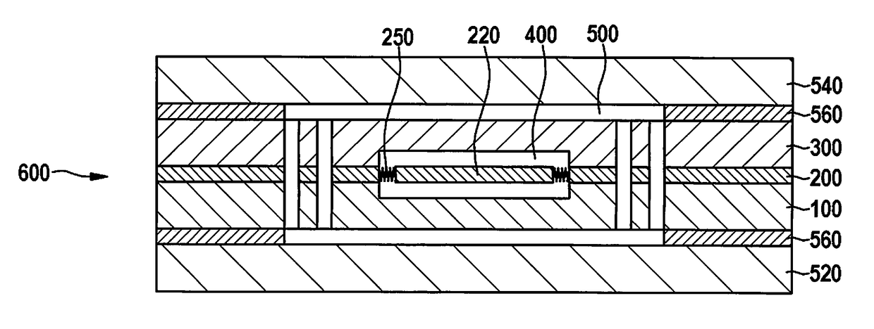
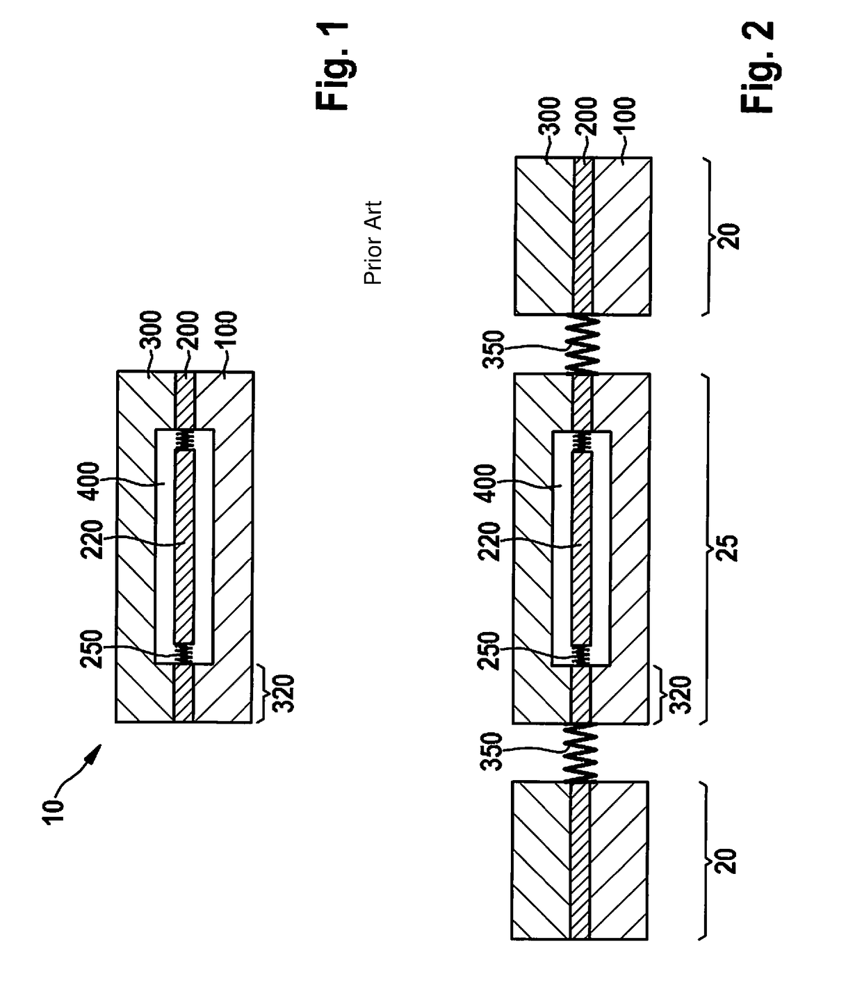
[0018]FIG. 1 shows a micromechanical device having a cavity in the related art. Shown is the schematic structure of a micromechanical device 10 in the form of a typical micromechanical yaw-rate or acceleration sensor. It is made up of at least one mobile micromechanical structure 220, which is produced in a functional plane 200 on substrate wafer 100. Micromechanical structure 220 is movably suspended with the aid of suspension springs 250. A wafer cap 300 protects this structure from the environment. A first cavity 400, inside which mobile structure 220 is situated, is formed between wafer cap 300 and substrate wafer 100. Wafer cap 300 and substrate wafer 100 are connected to each other with the aid of a sealing frame 320.

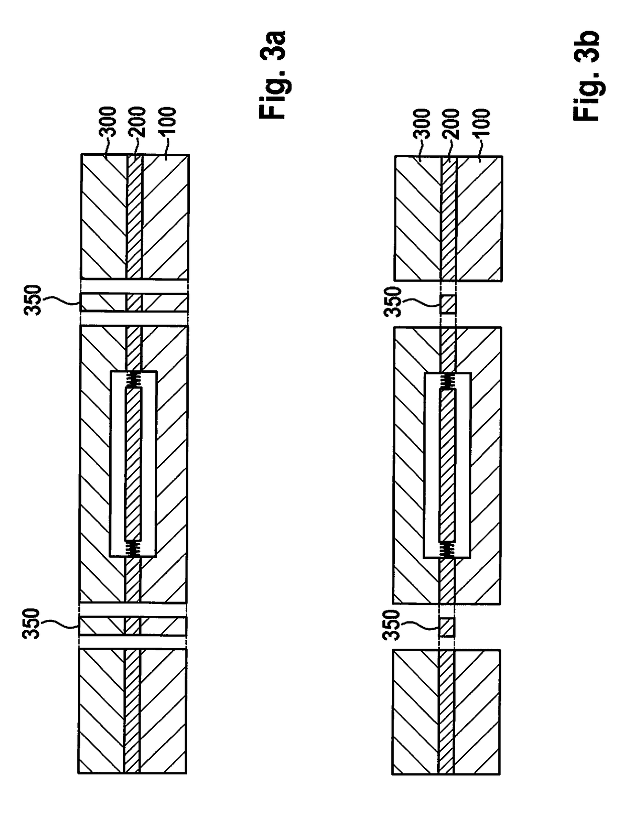
[0019]FIG. 2 schematically shows a micromechanical device having a cavity that is micromechanically decoupled, in a first specific embodiment of the present invention.

[0020]In contrast to the previously described micromechanical device in the related art, this mic...


PUM


Abstract

A micromechanical device having a substrate wafer, a functional layer situated above it which has a mobile micromechanical structure, and a cap situated on top thereof, having a first cavity, which is formed at least by the substrate wafer and the cap and which includes the micromechanical structure. The micromechanical device has a fixed part and a mobile part, which are movably connected to each other with at least one spring element, and the first cavity is situated in the mobile part. Also described is a method for producing the micromechanical device.

Description

RELATED APPLICATION INFORMATION[0001]The present application claims priority to and the benefit of German patent application no. 10 2016 206 791.5, which was filed in Germany on Apr. 21, 2016, the disclosure of which is incorporated herein by reference.FIELD OF THE INVENTION[0002]The present invention is based on a micromechanical device having a substrate wafer, a functional layer disposed thereon that includes a mobile micromechanical structure, and having a cap situated on top thereof, as well as a first cavity, which is formed at least by the substrate wafer and the cap and includes the micromechanical structure.BACKGROUND INFORMATION[0003]Micromechanical sensors for measuring the yaw rate or acceleration are made up of at least one mobile structure, which is insulated from the external environment inside a cavity. In most instances the mobile structure is produced on a substrate wafer employing surface-micromechanical technology. The cavity is produced by placing a wafer cap on...

Claims


Application Information

Patent Timeline
IPC IPC(8): B81B7/00B81C1/00
CPCB81B7/0016B81C1/00333B81B2201/0235B81C2203/0109B81B2203/0163B81B2203/0315B81B2201/0242B81B7/0048B81C2203/0118
Inventor ZUNFT, STEFFEN
Owner ROBERT BOSCH GMBH
Features
  • R&D
  • Intellectual Property
  • Life Sciences
  • Materials
  • Tech Scout
  • Unparalleled Data Quality
  • Higher Quality Content
  • 60% Fewer Hallucinations
Learn More