
Bracket anchor for fastening a facing in a supporting wall, and web plate of a bracket anchor

a technology for brackets and supporting walls, which is applied in the direction of covering/linings, constructions, building components, etc., can solve the problems of reducing stability, affecting the stability of the structure, and the vertical connection between the bracket head and the pressure element known from the prior art, so as to achieve a low degree of heat transfer and simple production

Active Publication Date: 2017-10-26
LEVIAT GMBH
View PDF32 Cites 3 Cited by
  • Summary
  • Abstract
  • Description
  • Claims
  • Application Information

AI Technical Summary

Benefits of technology

The invention is a bracket anchor that is easy to produce and has low heat transfer between the supporting wall and the facing. The bracket anchor has a connecting region that is substantially in the region of the support element and extends between the tension strut and the support element. The connecting region is designed to have a solid cross section with no interruption. The web plate of the bracket anchor is stable and fixes different shape support elements. The thin web plate has a reduced heat transfer and stability compared to thicker plates, but this is compensated by the angling of the compression strut. The bracket head can be fixed to the web plate in a simple manner through welding or with a closed underside. The invention also provides a design for a bracket anchor that reduces the potential for a lowered stability of the support angle.

Problems solved by technology

It has been shown that the vertical connection between bracket head and pressure element known from the prior art contributes only insignificantly, or not at all, to taking up the load.
As a result, the connecting region of tension strut and compression strut is situated partially, in particular completely, outside an insulation arranged between supporting wall and facing and does not contribute to the heat transfer between supporting wall and facing.
The comparatively small wall thickness of the web plate gives rise to reduced stability by comparison with thicker web plates.

Method used


Image

  • Bracket anchor for fastening a facing in a supporting wall, and web plate of a bracket anchor
  • Bracket anchor for fastening a facing in a supporting wall, and web plate of a bracket anchor
  • Bracket anchor for fastening a facing in a supporting wall, and web plate of a bracket anchor

Examples


Embodiment Construction

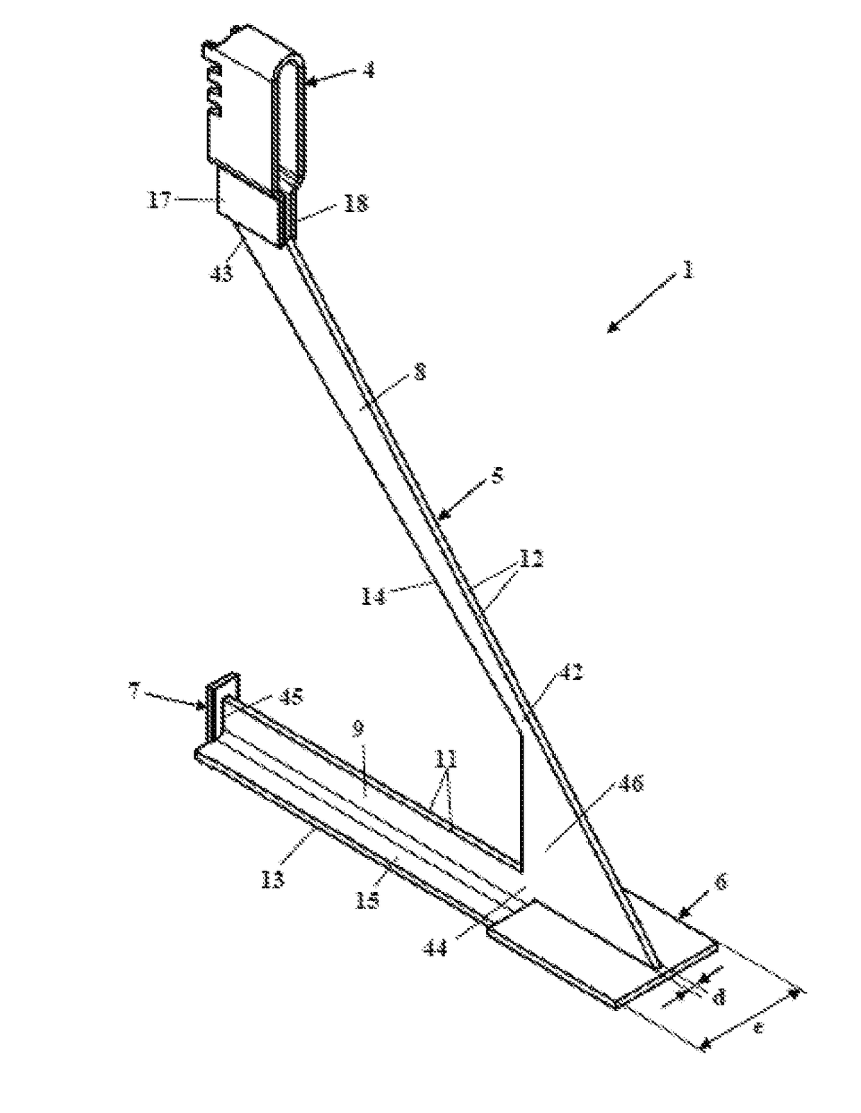
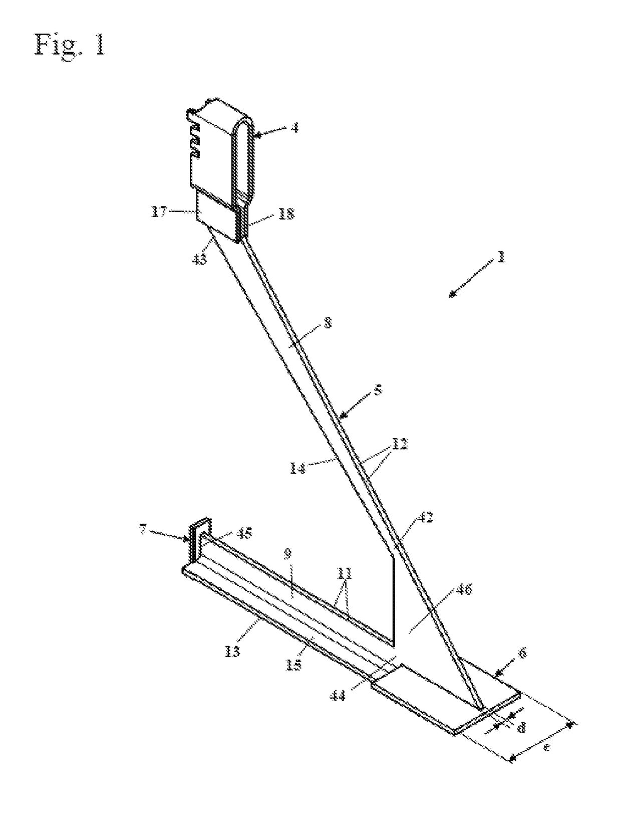
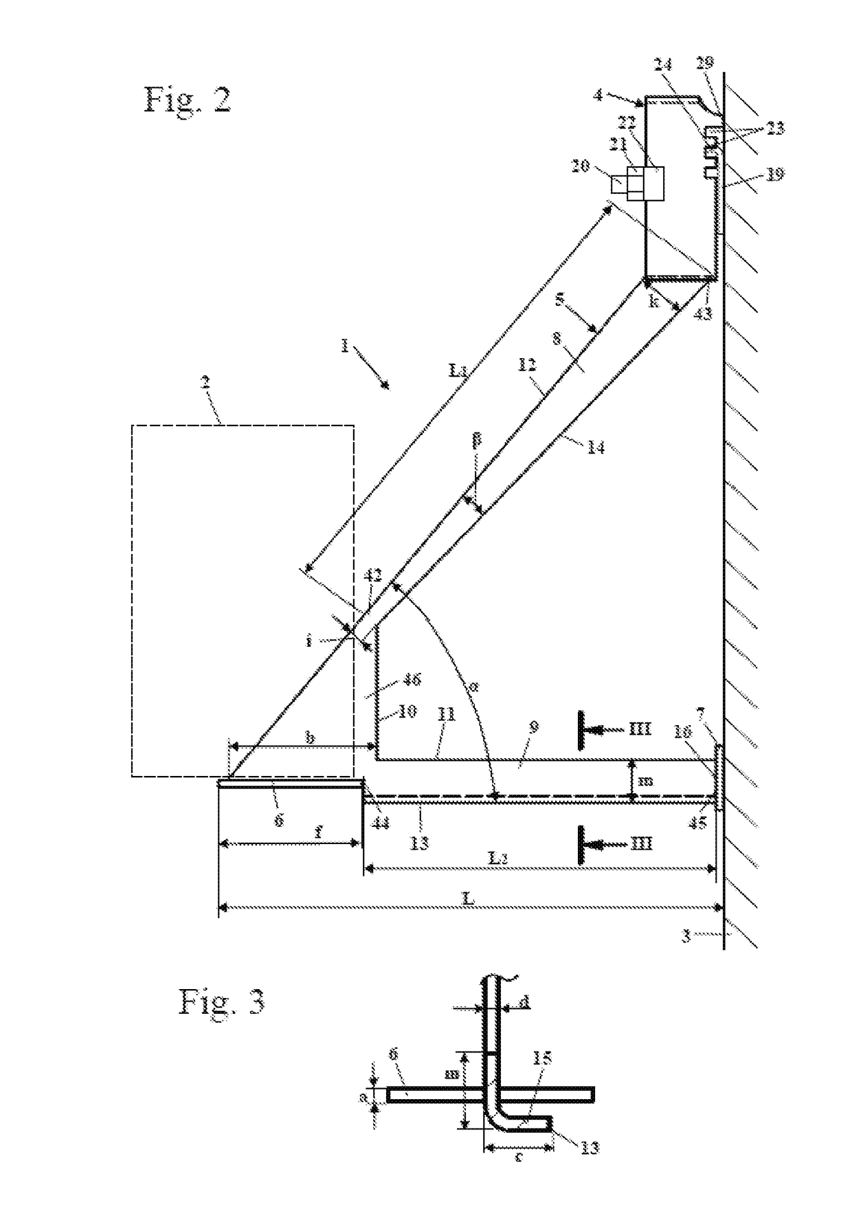
[0037]FIG. 1 shows a bracket anchor 1 in a perspective illustration. The bracket anchor 1 is provided to support a facing on a supporting wall. Between the supporting wall and the facing there is usually arranged insulating material in order to keep heat transfer from the facing to the supporting wall as low as possible. The bracket anchor 1 has a bracket head 4 which is provided for fixing to a supporting wall. The bracket head 4 is fixed to a web plate 5. The web plate 5 comprises a tension strut 8 which extends obliquely downward from the bracket head 4 relative to a supporting wall, and a compression strut 9 which, after mounting on a supporting wall, is usually oriented approximately horizontally. The tension strut 8 and the compression strut 9 are connected to one another at a connecting region 46. In the exemplary embodiment, the connecting region 46 has an approximately triangular shape. A support element 6, in the exemplary embodiment a planar support plate, is arranged at ...


PUM


Abstract

A bracket anchor for fastening a facing to a supporting wall has a bracket head for fastening the bracket anchor to the supporting wall, a web plate, a support element for supporting the facing, and a pressure element for transmitting pressure from the bracket anchor to the supporting wall. The support element and the pressure element are secured to the web plate. The entire web plate is formed from a single plate of constant wall thickness. The web plate includes a tension strut and a compression strut which are connected to one another only at their ends facing the support element and at most over half of the projecting length of the bracket anchor.

Description

CROSS-REFERENCE TO RELATED APPLICATIONS[0001]The present application claims priority of EP 16 167 150.8, filed Apr. 26, 2016, the priority of this application is hereby claimed and this application is incorporated herein by reference.BACKGROUND OF THE INVENTION[0002]The invention relates to a bracket anchor for fastening a facing to a supporting wall and to a web plate for a bracket anchor.[0003]DE 10 2010 051 557 A1 discloses a bracket anchor having a web plate which connects a bracket head, a support element and a pressure element to one another. The web plate is substantially triangular and has a circular opening for reducing thermal bridge losses.[0004]DE 10 2010 015 262 A1 presents a bracket anchor in which a threaded sleeve is welded to the web plate, an adjusting screw being screwed into said threaded sleeve and serving to support the bracket anchor on the supporting wall. This results in the bracket anchor having a comparatively complicated structure. The compressive forces ...

Claims


Application Information

Patent Timeline
IPC IPC(8): E04B1/41E04F13/08E04B1/38E04B1/76
CPCE04B1/40E04F13/0832E04B1/762E04B2103/06E04B2001/405E04F13/075E04F13/0857E04B1/388E04B2001/389
Inventor KASPRZAK, JAROSLAWPILCH, MARCINSTASKIEWICZ, JERZYALBARTUS, DIRKERZENGIN, ERTUGRULPIESKER, CAROLINEROIK, MATTHIASSTEGEMANN, MICHAEL
Owner LEVIAT GMBH
Learn More