
Resistance sensing mechanism for exercise equipment

a technology of resistance sensing and exercise equipment, which is applied in the direction of instruments, gymnastic exercise, sport apparatus, etc., can solve the problems of inconvenience to users and too much time to achieve one detection operation, and achieve the effect of shortening the sensing time, increasing the ease of operation, and effective reducing the itinerary of action

Active Publication Date: 2017-11-02
REXON IND CORP LTD
View PDF21 Cites 18 Cited by
  • Summary
  • Abstract
  • Description
  • Claims
  • Application Information

AI Technical Summary

Benefits of technology

The present invention provides a resistance sensing mechanism for exercise equipment that can reduce the time it takes to detect resistance changes. The mechanism includes a resistance adjusting unit and a sensor unit. The resistance adjusting unit has a holder frame, locating sleeve, adjustment screw rod, and screw nut. The sensor unit has first and second linkages, a sensor, and a sensible member. The first and second linkages pivotally connect to the screw nut and the locating sleeve, respectively. The sensor is mounted at one of the linkages and the sensible member is mounted at the other linkage. The sensor and the sensible member are positioned facing each other to generate a relative sensing signal. The arrangement of the linkages allows the sensor and the sensible member to move closer or farther from each other when resistance changes, resulting in faster sensing and easier operation.

Problems solved by technology

However, according to this prior art patent design, the main sensor is movable but the sensible member is immovable, thus, it takes too much time to achieve one detection operation.
So, in actual operation, it is likely the detection of the resistance causes inconvenience to the user.

Method used


Image

  • Resistance sensing mechanism for exercise equipment
  • Resistance sensing mechanism for exercise equipment
  • Resistance sensing mechanism for exercise equipment

Examples


Embodiment Construction

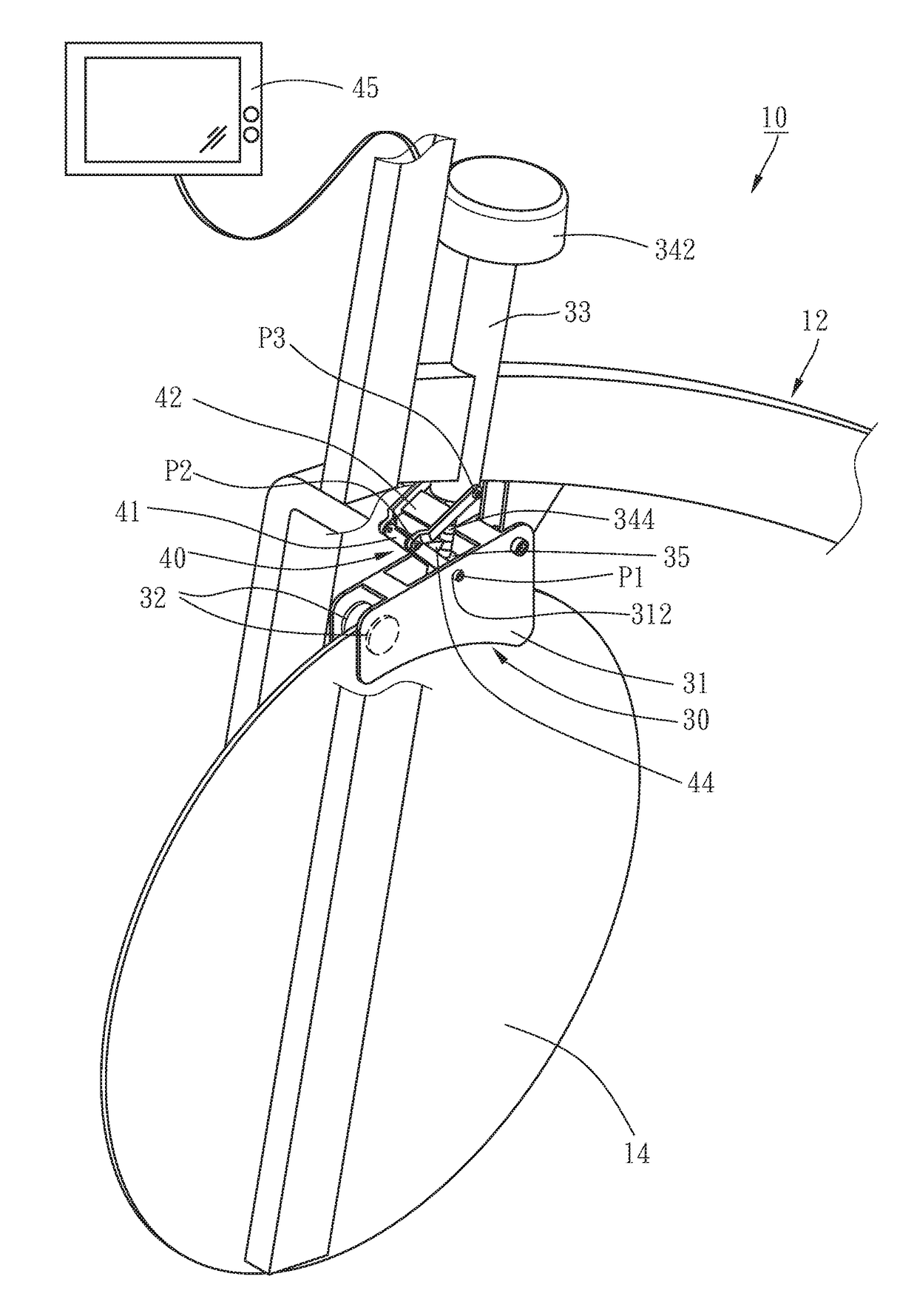
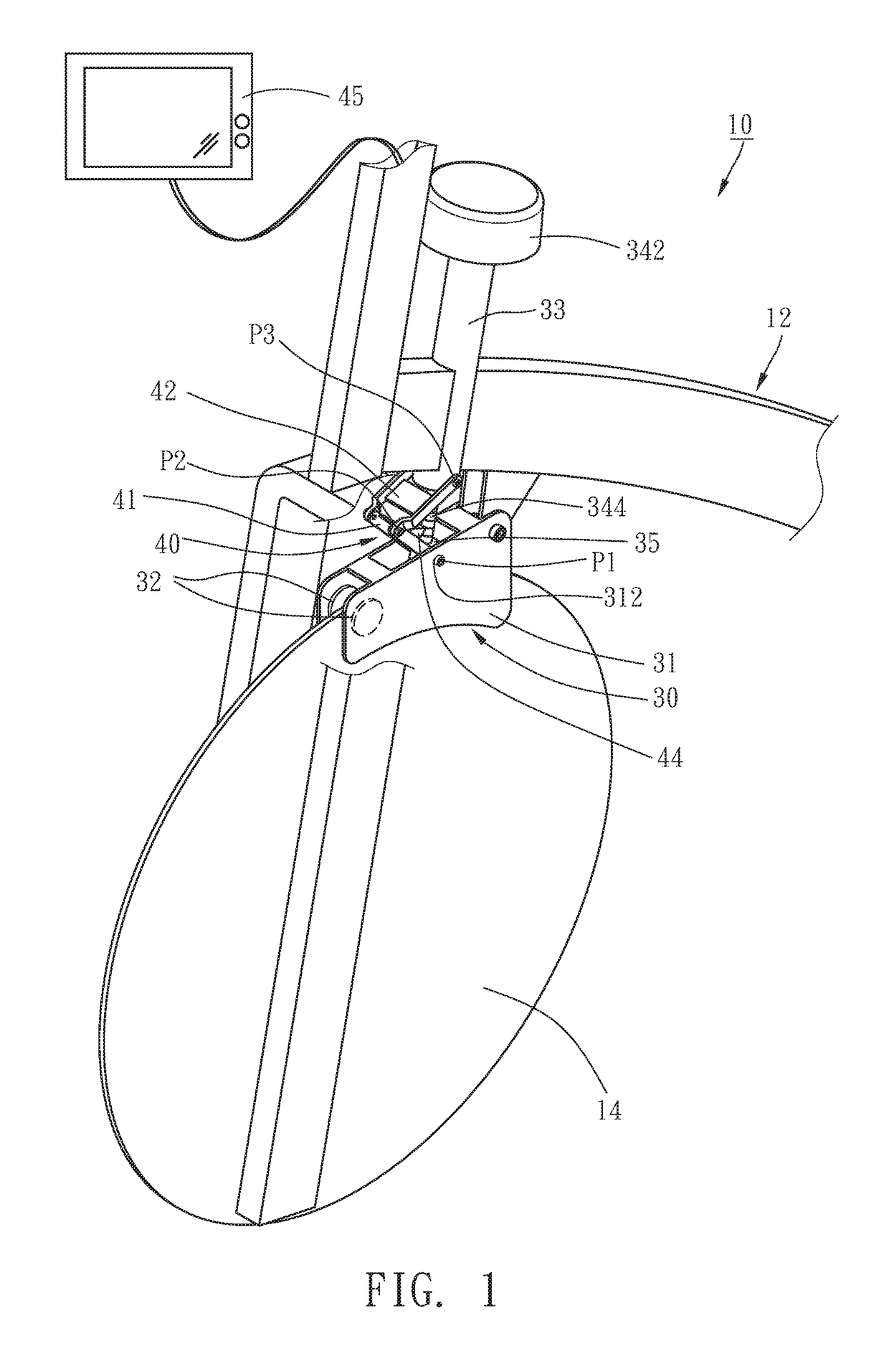
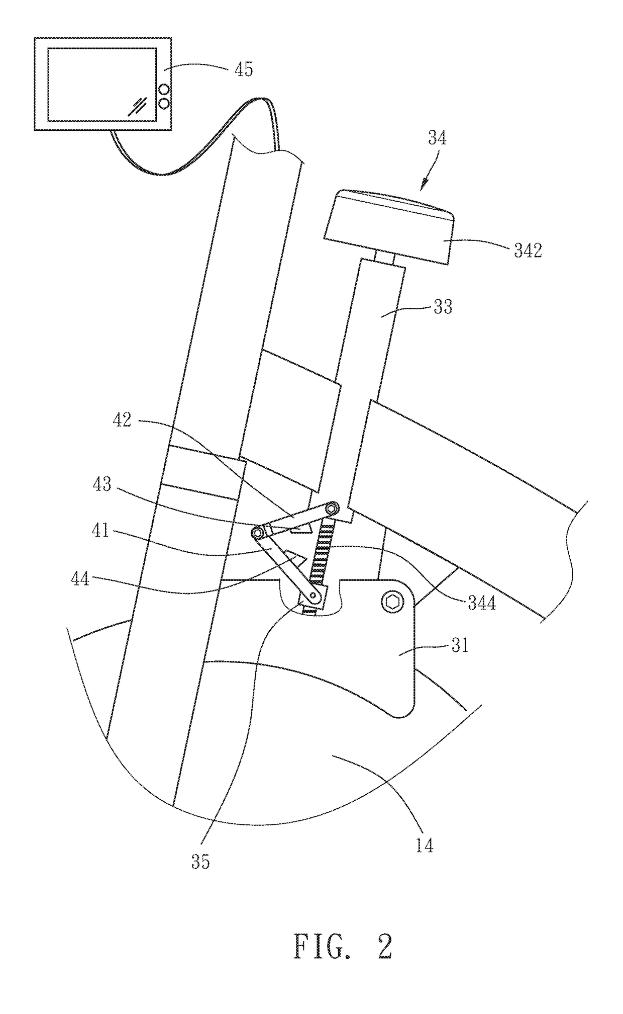
[0011]Referring to FIG. 1, a resistance sensing mechanism 10 for exercise equipment in accordance with the present invention is shown. The exercise equipment comprises a bicycle frame 12 and a flywheel 14 rotatably mounted at the bicycle frame 12. The resistance sensing mechanism 10 comprises a resistance adjusting unit 30 and a sensor unit 40.

[0012]The resistance adjusting unit 30 comprises a holder frame 31, two opposing magnetic members 32, a locating sleeve 33, an adjustment screw rod 34, and a screw nut 35. The holder frame 31 is disposed around the outer perimeter of the flywheel 14 and pivotally connected with a rear end thereof to the bicycle frame 12, having two elongated slots 312 respectively cut through two opposite sidewalls thereof. The magnetic members 32 are bilaterally mounted in the holder frame 31 for allowing the flywheel 14 to rotate therebetween. The locating sleeve 33 is affixed to the bicycle frame 12 and disposed above the holder frame 31. The adjustment scr...


PUM

PropertyMeasurementUnit
resistanceaaaaaaaaaa
damping resistanceaaaaaaaaaa
degree of resistanceaaaaaaaaaa

Abstract

A resistance sensing mechanism including a resistance adjusting unit including a holder frame, a locating sleeve disposed above the holder frame, an adjustment screw rod rotatably inserted through the locating sleeve and a screw nut threaded onto the adjustment screw rod and pivotally connected to the holder frame, and a sensor unit including a first linkage pivotally connected with one end to the screw nut, a second linkage having one end pivotally connected to an opposite end of the first linkage and an opposite end pivotally connected to the locating sleeve, a sensor mounted at one of the first and second linkages and a sensible member mounted at the other of the first and second linkages to face toward the sensor. Subject to the linkage relationship between the first and second linkages, the distance between the sensor and the sensible member can be changed, thereby generating a relative sensing signal.

Description

BACKGROUND OF THE INVENTIONField of the Invention[0001]The present invention relates to exercise equipment technology and more particularly, to a resistance sensing mechanism for use in an exercise equipment.Description of the Related Art[0002]In order to allow the user to easily adjust the operation of an exercise machine according to personal training needs, the exercise equipment is generally equipped with a damping resistance adjuster. Through the damping resistance adjuster, the user can adjust the damping resistance to the flywheel or other similar elements. Further, in order to allow the user to accurately control the resistance given by the damping resistance adjuster during the adjustment operation, some exercise equipments may be configured to provide a sensing mechanism for sensing the degree of resistance given by the damping resistance adjuster. Subject to the detection of the sensing mechanism, the user can adjust the damping resistance at the appropriate time.[0003]In...

Claims


Application Information

Patent Timeline
Patent Type & Authority Applications(United States)
IPC IPC(8): A63B24/00A63B22/06A63B21/22G01L1/12G01D5/14
CPCA63B24/0087A63B21/225A63B2220/80G01D5/145G01L1/12A63B22/0605A63B21/00069A63B21/0051A63B71/0622A63B2209/08A63B2220/20A63B2220/51A63B2220/58A63B2220/833A63B2220/89G01L3/22
Inventor CHANG, YAO-JEN
Owner REXON IND CORP LTD
Learn More