Container Having Multiple Layers of Dunnage, At Least One Layer Having At Least One Lockable Crossbar Assembly

a crossbar assembly and container technology, applied in the field of containers for shipping, can solve the problems of unsatisfactory operation, difficult and time-consuming removal of parts in containers, and undesirable delay in accessing and removing parts from containers, so as to achieve efficient and safe removal, without unnecessary stress or strain on the operator

Active Publication Date: 2017-11-02
BRADFORD CO
View PDF6 Cites 2 Cited by
  • Summary
  • Abstract
  • Description
  • Claims
  • Application Information

AI Technical Summary

Benefits of technology

The invention is a container designed to make it easier and safer for operators to load and unload products. The container has movable tracks and crossbar assemblies that can be locked or unlocked to create secure positions for the dunnage supporting the product. The container also has a movable shelf assembly for easier unloading and a design that allows for efficient and safe loading and unloading of products without excessive stress on the operator. The container is made of plastic or any other suitable material and has non-linear tracks along which the dunnage supports and crossbar assembly move. The end members of the dunnage supports and crossbar assembly are designed to prevent dunnage material from entering the tracks.

Problems solved by technology

Some existing containers are difficult to access, which makes removal of the parts therein difficult and time-consuming.
Any delay in access and removal of the part from the container is undesirable.
However, the installation of such turntables adds to the cost of production, takes up valuable floor space and reduces plant flexibility.
The size and / or weight of the parts or workpieces may cause stress or strain on the line worker and, more particularly, on the back of the worker when inserting or removing parts from such a container.
Such ergonomically unfriendly movements may cause physical trauma, pain and other injuries that may lead to lost production time.
This requires space around the container which may not be available, depending on the physical layout of the plant or facility.
The length (front to back) of certain containers may be limited because the container manufacturer needs to eliminate the need for a line worker to walk around the container to remove product from inside the container.
The more containers needed to ship a predetermined number of parts, the greater the cost to the shipper.
This movement by the line worker is ergonomically unfriendly because the line worker must lean forward and bend down and lift a part up and over a wall into the container to remove the part from inside the container.
Similarly, when a part must be inserted into a container, the line worker may have to lean forward and insert the part, which may be heavy, into its proper location inside the container, again experiencing ergonomically unfriendly movements.
Depending upon the number of times the line worker repeats this unnatural motion into the interior of the container, strain in the back, legs and arms may result.
The size and / or weight of the parts may increase the strain on the line worker.
Thus, simply removing multiple parts during a work day may cause physical trauma, pain and other injuries that may lead to lost production time.
However, in any of the containers identified above, when the container is empty or partially empty of products, the movable crossbar assemblies, and dunnage suspended by such crossbar assemblies, may undesirably move inside the container during shipment, possibly creating noise and potentially damaging a portion of the container.

Method used


Image

  • Container Having Multiple Layers of Dunnage, At Least One Layer Having At Least One Lockable Crossbar Assembly
  • Container Having Multiple Layers of Dunnage, At Least One Layer Having At Least One Lockable Crossbar Assembly
  • Container Having Multiple Layers of Dunnage, At Least One Layer Having At Least One Lockable Crossbar Assembly

Examples


Embodiment Construction

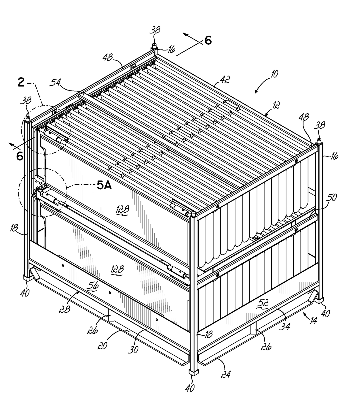
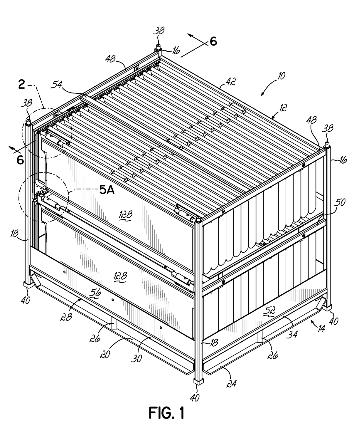
[0096]Referring to FIG. 1, there is illustrated one embodiment of reusable and returnable container 10 for holding products 5 therein. The reusable and returnable container 10, as shown, comprises an outer metal frame 12 having a base 14, two rear corner posts 16 and two front corner posts 18, all four corner posts 16, 18 extending upwardly from the base 14.

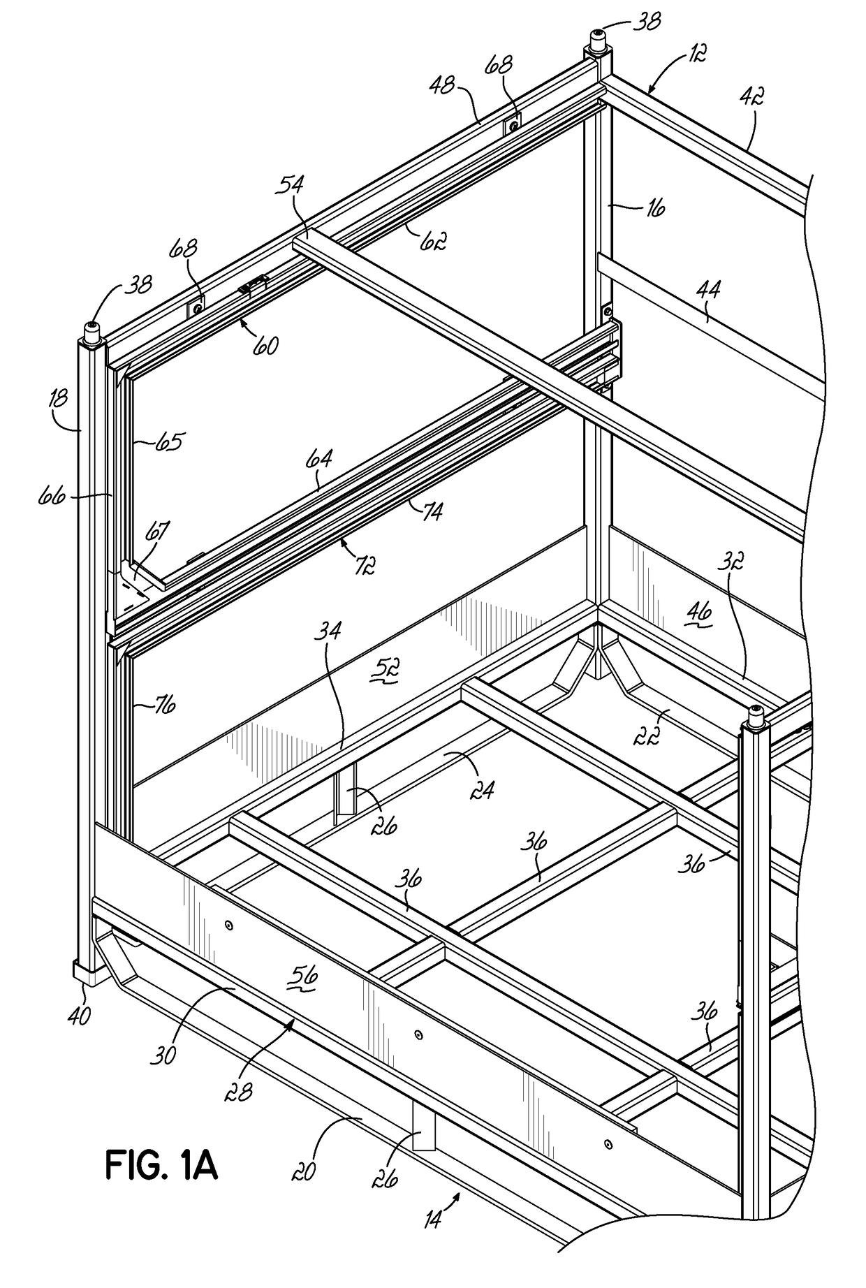
[0097]As best shown in FIG. 1A, the base 14 of outer metal frame 12 is generally rectangular in shape and comprises a front perimeter member 20, a rear perimeter member 22 and two side perimeter members 24 (only one being shown). The perimeter members 20, 22 and 24 of the base 14 may be secured together or secured to the rear corner posts 16 and front corner posts 18 via any conventional means, including welding. A plurality of stubs 26 extend upwardly from the base 14 and are secured thereto via any conventional means, including welding.

[0098]As best shown in FIG. 1A, a generally rectangular sub-base 28 is spaced above the base ...


PUM


Abstract

A container for holding product therein during shipment and for reuse has multiple levels of tracks supported by each side of the container. At least one of the tracks on each side may be linear, generally U-shaped and / or L-shaped. Dunnage supports and at least one lockable crossbar assembly travel along corresponding tracks at the same level. At least one lockable crossbar assembly has locking assemblies to fix the position of the lockable crossbar assembly relative to the tracks. Dunnage hangs from at least some of the dunnage supports for supporting products.

Description

[0001]This application claims the benefit of U.S. Provisional Patent Application Ser. No. 62 / 328,683 filed Apr. 28, 2016 and U.S. Provisional Patent Application Ser. No. 62 / 407,149 filed Oct. 12, 2016 and U.S. Provisional Patent Application Ser. No. 62 / 415,593 filed Nov. 1, 2016. Each of these applications is fully incorporated by reference.FIELD OF THE INVENTIONField of the Invention[0002]The present invention relates to containers for use in shipping and, more particularly, to containers with lockable crossbar assemblies for supporting dunnage for shipping and storing products.Background of the Invention[0003]Different container structures are utilized by manufacturers to ship a variety of different products to end users, which may be, for example, assembly plants. In the automobile industry, for example, an assembly plant assembling a particular automobile might utilize a number of different parts from different manufacturers. These manufacturers ship their respective parts to th...

Claims


Application Information

Patent Timeline
IPC IPC(8): B65D88/54B65D19/18B65D85/68
CPCB65D88/546B65D19/18B65D85/68B65D2519/00273B65D2585/6887B65D2519/00805B65D2519/00069B65D2519/00174B65D2519/0082B65D19/06B65D19/44B65D2519/00024B65D2519/00034B65D2519/00059B65D2519/00094B65D2519/00233B65D2519/00293B65D2519/00323B65D2519/00333B65D2519/00338B65D2519/00373B65D2519/00422B65D2519/00532B65D2519/00562B65D2519/00621B65D2519/00666B65D2519/00701B65D2519/0081B65D2519/0097B65D81/05
Inventor BRADFORD, JUDSON A.BURNS, ALLEN L.SANGER, MATTHEW S.
Owner BRADFORD CO
Why Eureka
Try Eureka