Differential force and touch sensing

a technology of touch and force, applied in the field of capacitive sensing, can solve the problems of less space available for other components, add to the thickness and/or size of touch and/or force sensing components, and increase so as to increase the accuracy of correlation and reduce the latency of reporting

Active Publication Date: 2017-11-02
SYNAPTICS INC
View PDF4 Cites 16 Cited by
  • Summary
  • Abstract
  • Description
  • Claims
  • Application Information

AI Technical Summary

Benefits of technology

[0006]This disclosure generally provides input devices, processing systems and methods for differential touch and force sensing using anti-guarding and simultaneous touch and force sensing using both in-phase and quadrature (I/Q) demodula...

Problems solved by technology

The force sensor electrodes and associated routing undesirably add manufacturing and material cost for fabrication of the input device, and often undesirably add to the thickness and or size of the touch and/or force sensing components.
Moreover, adding routing for addit...

Method used


Image

  • Differential force and touch sensing
  • Differential force and touch sensing
  • Differential force and touch sensing

Examples


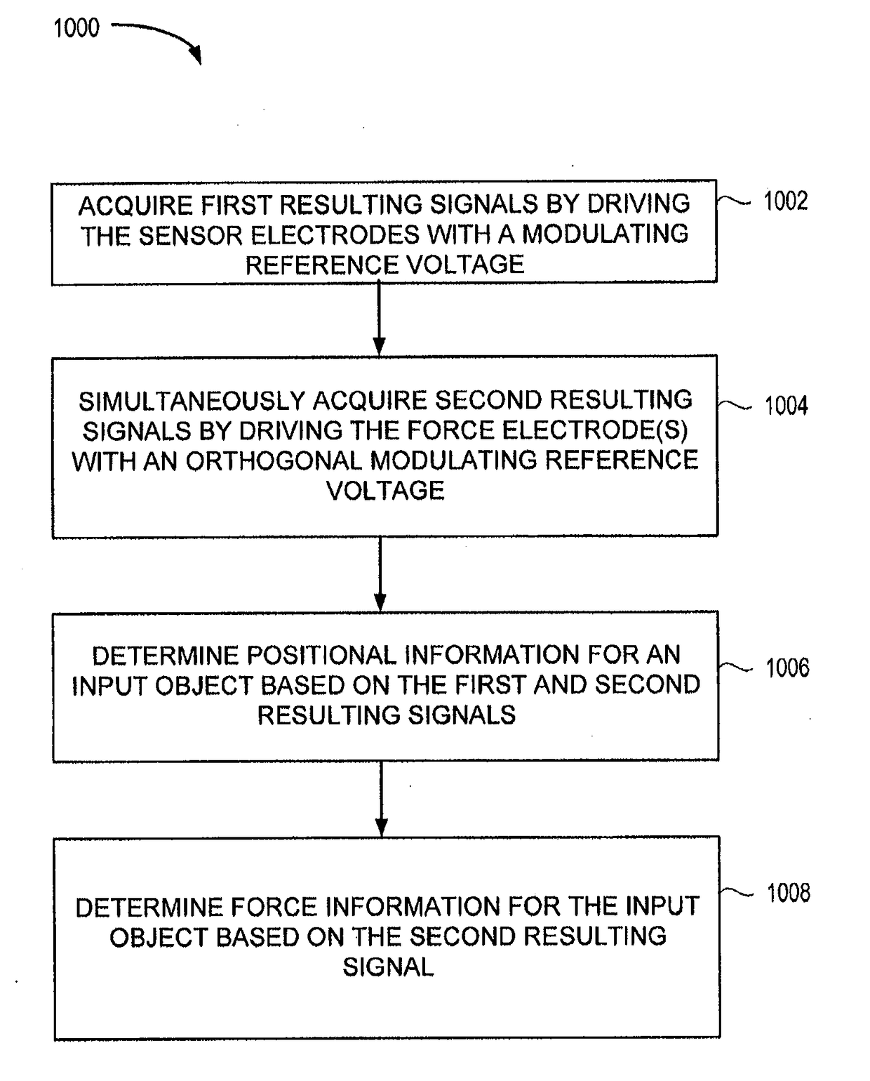
example simultaneous

Touch and Force Sensing Using In-Phase Quadrature Demodulation

[0090]Typically, the touch signal (e.g., the finger signal) is detected by measuring the background capacitance and filtering it to estimate a baseline, and subtracting the baseline capacitance from all subsequent measurements to get the “future” finger signals. According to the techniques provided herein, the background capacitance may be measured simultaneously and independently with the finger signal.

[0091]FIG. 7 is a block diagram depicting a simplified cross-section of an input device 700 showing driving the sensor and force electrodes with a modulated sensing signal to acquire touch-to-sensor capacitive coupling and background capacitance, according to an aspect. As shown in FIG. 7, the baseline or background capacitance, Cb, carries deflection information (e.g., due to force of touch) between the touch sensor electrodes 714 and the display chassis / ground 712. Cb is an additive quantity to the touch-to-sensor coupli...


PUM


Abstract

An input device is configured to detect force being applied to an input region of the device by an input object, in addition to the position of the input object using touch sensing methods. Aspects include driving a force sensing electrode of the input device using an anti-guarding voltage alternating with a ground or guard voltage, while driving the touch sensing electrodes with a reference voltage, to obtain touch measurements, force measurements, interference measurements, double the force signal, and/o double the touch signal for differential touch and force detection. Aspects also include driving sensor electrodes using orthogonal signals and performing in-phase and quadrature demodulation of the received signal for simultaneous and independent touch and force measurements.

Description

CROSS-REFERENCE TO RELATED APPLICATION(S)[0001]This application claims the benefit of U.S. Provisional Application No. 62 / 330,042, filed Apr. 29, 2016, the entire contents of which are incorporated by reference herein.BACKGROUNDField of the Disclosure[0002]Aspects of this disclosure generally relate to capacitive sensing and, more particularly, sensing touch and force on an input surface using capacitive sensing.Description of the Related Art[0003]Input devices including proximity sensor devices (also commonly called touchpads or touch sensor devices) are widely used in a variety of electronic systems. A proximity sensor device typically includes a sensing region, often demarked by a surface, in which the proximity sensor device determines the presence, location and / or motion of one or more input objects. Proximity sensor devices may be used to provide interfaces for the electronic system. For example, proximity sensor devices are often used as input devices for larger computing sys...

Claims


Application Information

Patent Timeline
IPC IPC(8): G06F3/041G06F3/044
CPCG06F3/0414G06F3/044G06F2203/04107G06F2203/04108G06F3/0418G06F2203/04105G06F3/0412G06F3/0416G06F2203/04106G06F3/0446G06F3/0443
Inventor REYNOLDS, JOSEPH KURTH
Owner SYNAPTICS INC
Why Eureka
Try Eureka