
Display method of on-screen keyboard, and computer program product and non-transitory computer readable medium of on-screen keyboard

Active Publication Date: 2017-11-02
YAO BING YANG
View PDF20 Cites 26 Cited by
  • Summary
  • Abstract
  • Description
  • Claims
  • Application Information

AI Technical Summary

Benefits of technology

The invention provides a better way to use a computer's on-screen keyboard by showing both the keys and the positions they are in. This means that the user doesn't have to look at a physical keyboard while typing, which makes it faster.

Problems solved by technology

Although a physical keyboard may be replaced with the conventional on-screen keyboard to type data, unless a touch-screen on which keys may be clicked by using fingers is used, a data typing speed is extremely slow when keys are clicked one by one by using a mouse.
The conventional on-screen keyboard is not suitable to be used in continuously typing a large amount of data.
Although the user can also enable the conventional on-screen keyboard and type data by using the physical keyboard, it does not make sense due to the conventional on-screen keyboard lacks of the feedback of “a finger standby position” of the user on the physical keyboard in real time.
None of the prior arts used the on-screen keyboard technology nor improved it.
If image processing of a semi-transparency effect is performed on the real image, the distortion is dramatically increased, probably resulting in that a finger position in the image is not easy to be recognized.
But if the image processing of the semi-transparency effect is not performed on the real image, the real image occupies large space of a visible display area (the real image will completely block the lower overlap screen).
Moreover, user would feel strange or unexpected if the virtual images (virtual reality images or game images) and the real images (real keyboard images) are mixed together on the display screen.
More importantly, real-time image processing needs to consume a large quantity of hardware resources and easily affects performance of the system.
In the prior art 2, the gesture operation range is approximately 4 inches above the keyboard, and the gesture operations have no connection with the keys on the physical keyboard, thus cannot be combined with the on-screen keyboard technology, cannot accelerate a speed of data typing of a user by using the physical keyboard, and cannot assist the user in training of touch-typing (typing without staring at the keyboard).
In addition, the camera lenses of prior arts may misjudge a finger position, but the prior arts lack of a method for correcting the misjudgment.
Besides, when ambient light sources are insufficient, the camera lenses of prior arts may not able to capture the image.

Method used


Image

  • Display method of on-screen keyboard, and computer program product and non-transitory computer readable medium of on-screen keyboard
  • Display method of on-screen keyboard, and computer program product and non-transitory computer readable medium of on-screen keyboard
  • Display method of on-screen keyboard, and computer program product and non-transitory computer readable medium of on-screen keyboard

Examples


first embodiment

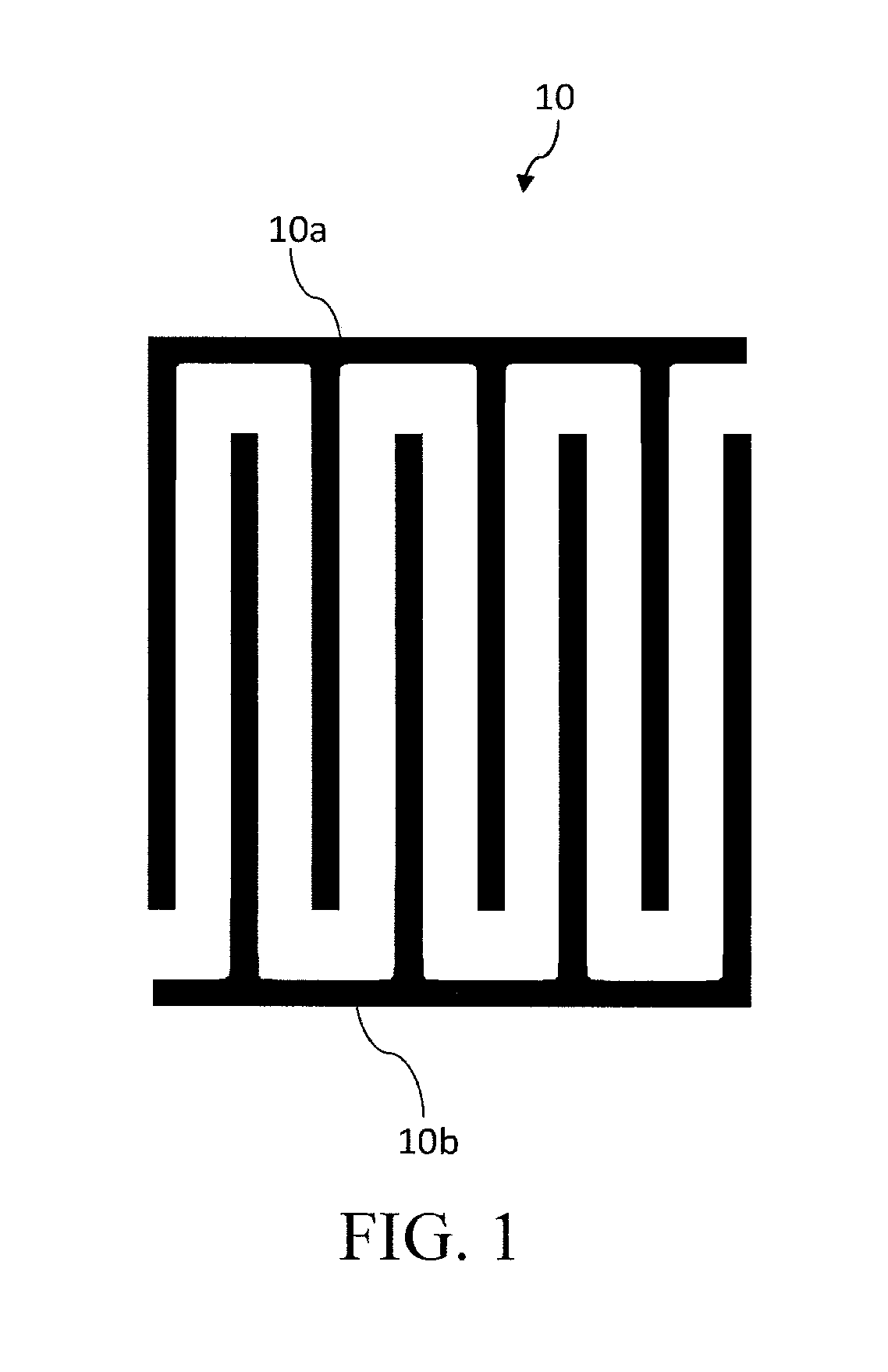
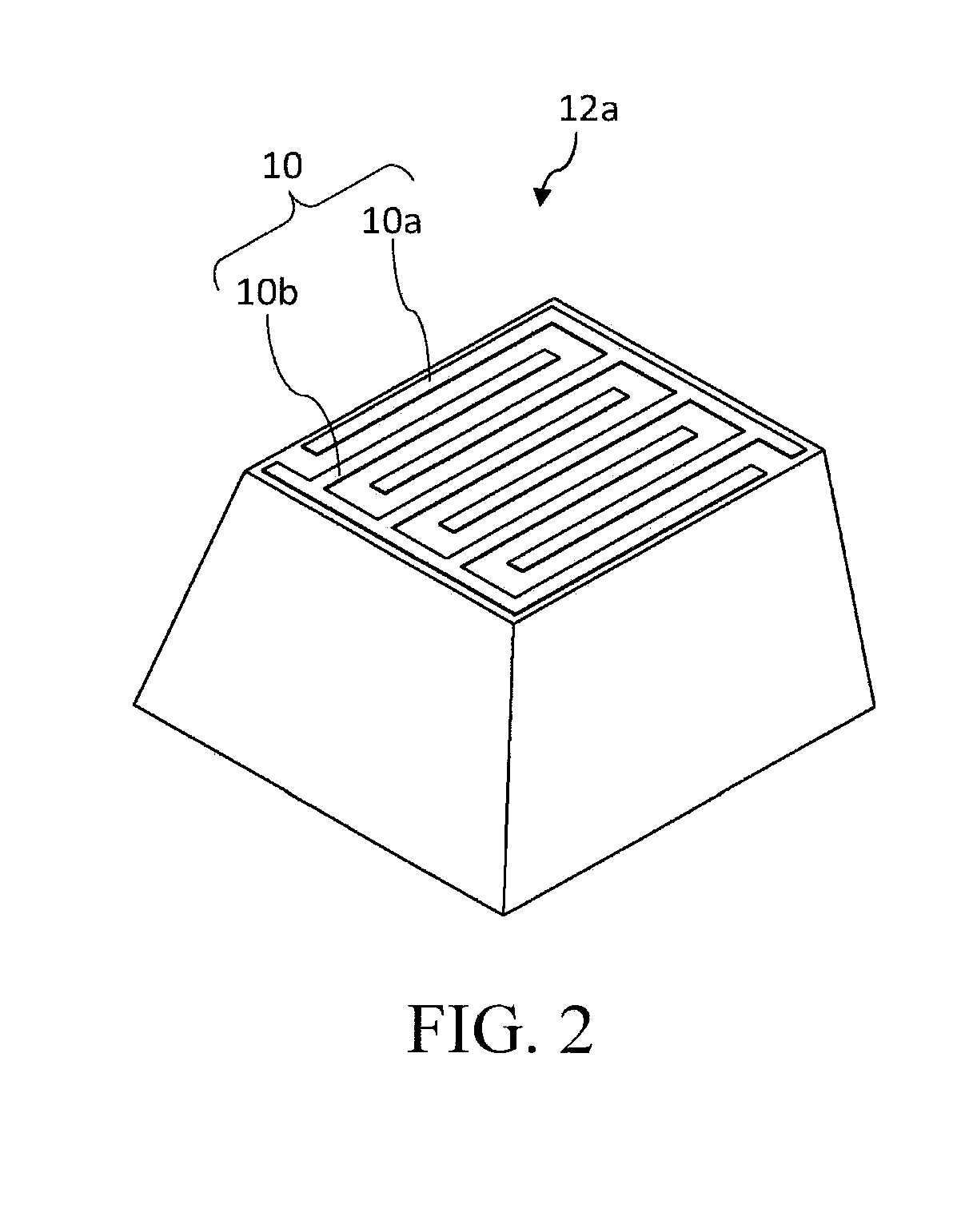
[0047]Referring to FIG. 5, FIG. 5 is an axonometric view of a physical keyboard 18 according to the present invention. For convenience of description below, the physical keyboard 18 in the figure is obtained after some keycaps 12a are removed to display structures of a supporting plate 20 and supporting housings 22a below the keycap 12a. In some embodiments, the supporting plate 20 is a part of an upper case (also referred to as a top-cover) of the physical keyboard 18, that is, the supporting plate 20 and the physical keyboard 18 are an integral located on an upper surface of the physical keyboard 18. In other embodiments, the supporting plate 20 is located at a lower layer of the upper case of the physical keyboard 18. The supporting plate 20 of both embodiments is provided with the supporting housing 22a, and the supporting plate 20 is formed integrally with the supporting housings 22a. Apart from the keycap 12a, the supporting plate 20, and the supporting housing 22a, the physic...

third embodiment

[0059]Referring to FIG. 13, FIG. 13 is schematic disassembled axonometric view of a keycap 12c of a physical keyboard 18 according to the present invention. A letter / number / symbol mark (a letter “A” herein in capital) may be printed on a side surface (that is, a side facing a user) of the keycap 12c neighboring to the side of the touch key part 10. In addition, a covering layer 62 may also be disposed on the keycap 12c to protect the touch key part 10. In some embodiments, a letter / number / symbol mark represented by each key may be printed on the upper part (not shown) of the keycap 12c. In this case, a transparent or colored covering layer 62 may be disposed on the keycap 12c, and the letter / number / symbol mark represented by each key may be printed on the covering layer. Alternatively, the letter / number / symbol mark represented by each key may be printed on the keycap 12c first, and then a transparent covering layer 62 may be provided.

[0060]Referring to FIG. 14, FIG. 15 and FIG. 16 t...


PUM


Abstract

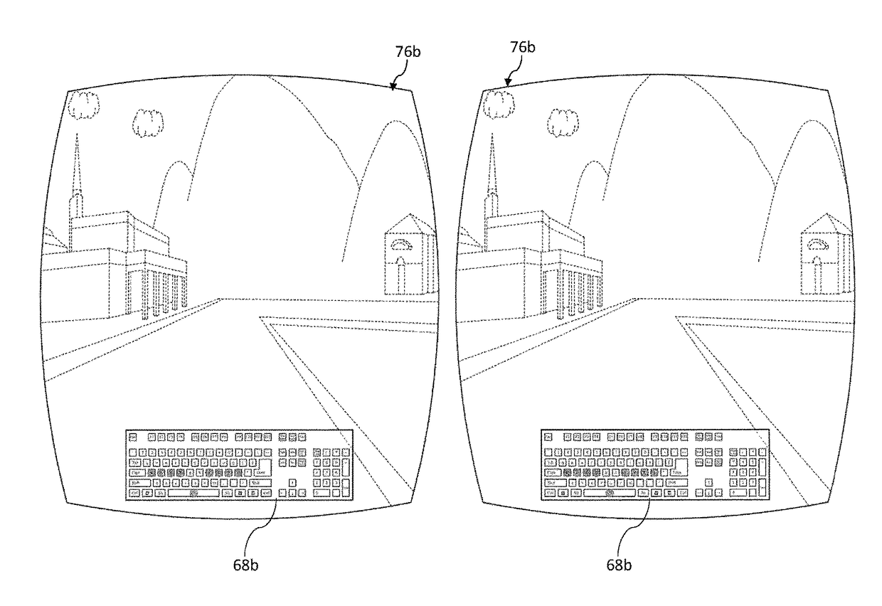
A method for displaying an on-screen keyboard is applied a computing device connected to a physical keyboard and a screen, where the physical keyboard includes a plurality of keycaps capable of responding to a touch on the keycap to output a first key signal and responding to a keystroke on the keycap to output a second key signal to the computing device, and the method for displaying an on-screen keyboard includes: displaying an on-screen keyboard on a topmost layer of a display image of the screen; reading the first key signal output by the physical keyboard corresponding to the touch on the keycap; and displaying, according to the first key signal, a first key mark at a position corresponding to the touched keycap on the on-screen keyboard.

Description

CROSS-REFERENCE TO RELATED APPLICATION[0001]This non-provisional application claims priority under 35 U.S.C. §119(a) to Patent Application No. 105113618 filed in Taiwan, R.O.C. on Apr. 29, 2016, the entire contents of which are hereby incorporated by reference.BACKGROUNDTechnical Field[0002]The present invention relates to a data typing and display method of computing devices such as a computer, a mobile device, or a head-up display / head-mounted display / virtual reality display device, and in particular, to a method for displaying an on-screen keyboard, and a computer program product of the on-screen keyboard.Related Art[0003]An on-screen virtual keyboard, alternatively referred to as an on-screen keyboard (OSK for short). In Microsoft Windows operating systems, such as Windows 7, Windows 8, and Windows 10, enabling the small screen keyboard is that “a Win key+an X key” are simultaneously depressed, click on “execute”, and then enter “osk”; alternatively, the “on-screen keyboard” is ...

Claims


Application Information

Patent Timeline
IPC IPC(8): G06F3/0488G06F3/02
CPCG06F3/02G06F3/04886G06F3/0202G06F3/041G06F3/1407H01H13/705H01H2219/0026H01H2219/028H01H2225/028H01H2239/006
Inventor YAO, BING-YANG
Owner YAO BING YANG
Learn More