Thin Film Magnetic Head, Head Gimbals Assembly, Head Arm Assembly, And Magnetic Disk Unit

Active Publication Date: 2017-11-02
TDK CORPARATION +1
View PDF1 Cites 0 Cited by
  • Summary
  • Abstract
  • Description
  • Claims
  • Application Information

AI Technical Summary

Benefits of technology

The invention relates to a thin film magnetic head for detecting contact between the head and a magnetic disk. The head includes a magnetic material layer with a structure that stabilizes the magnetic domain structure, reducing variations in the magnetic domain structure due to external disturbances. This prevents noise in the detection process and allows for accurate detection of contact between the head and the medium. The magnetic material layer has an opening that increases the detection sensitivity, and a heating element can be added to control the floating height of the head slider with higher accuracy. The invention also provides a method for manufacturing the thin film magnetic head that improves detection accuracy and increases the life of the magnetic material layer.

Problems solved by technology

When the recording track width is reduced, the size of the thin film magnetic head is also reduced, which weakens the signal recording ability of the magnetic recording element on the magnetic disk and weakens the intensity of signal magnetic field from the magnetic disk.
Under the circumstances, the floating height of the entire magnetic head slider has been reduced, but sufficient control has not been achieved, which has brought the thin film magnetic head into contact with a part such as a fine projection on the surface of the magnetic disk, thereby causing issues such as occurrence of an abnormal signal due to heat generation, and abrasion of the thin film magnetic head itself.

Method used


Image

  • Thin Film Magnetic Head, Head Gimbals Assembly, Head Arm Assembly, And Magnetic Disk Unit
  • Thin Film Magnetic Head, Head Gimbals Assembly, Head Arm Assembly, And Magnetic Disk Unit
  • Thin Film Magnetic Head, Head Gimbals Assembly, Head Arm Assembly, And Magnetic Disk Unit

Examples


first modification

(First Modification)

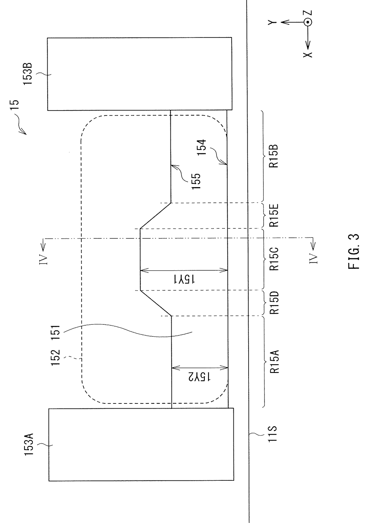
[0063]Further, various modifications may be made on the configuration (the shape) of the main part of the thin film magnetic head. A modification of the thin film magnetic head according to the above-described embodiment is described below. FIG. 6 is a plan view illustrating a resistance sensor 15A as a modification of the above-descried embodiment, and corresponds to FIG. 3 of the above-described embodiment (the resistance sensor 15).

[0064]The resistance sensor 15 of the above-described embodiment has the antiferromagnetic material layer forming the laminated body with the magnetic material layer, as the magnetic-domain stabilizing structure. In contrast, the resistance sensor 15A of the present modification has an opening 151K passing through the magnetic material layer 151 in a thickness direction, as a magnetic-domain stabilizing structure.

[0065]In this way, the opening 151K is provided, in particular, in the central region R15C where a change in the magnetic...

second modification

(Second Modification)

[0066]Note that the shape of the opening 151K is not limited to a circular shape illustrated in FIG. 6, and, for example, a polygon-shaped opening 151K of a resistance sensor 15B illustrated in FIG. 7 may be adopted.

third modification

(Third Modification)

[0067]The magnetic material layer 151 may also be variously modified. For example, as represented by a resistance sensor 15C illustrated in FIG. 8, the magnetic material layer 151 including the central region R15C and the end regions R15A and R15B located next to respective sides of the central region R15C may be provided. In the present modification, the backward edge 155 is inclined to the forward edge 154 in the end regions R15A and R15B.

[0068]The correspondence relationships between the reference numerals and the components of the present embodiment are collectively illustrated as follows.

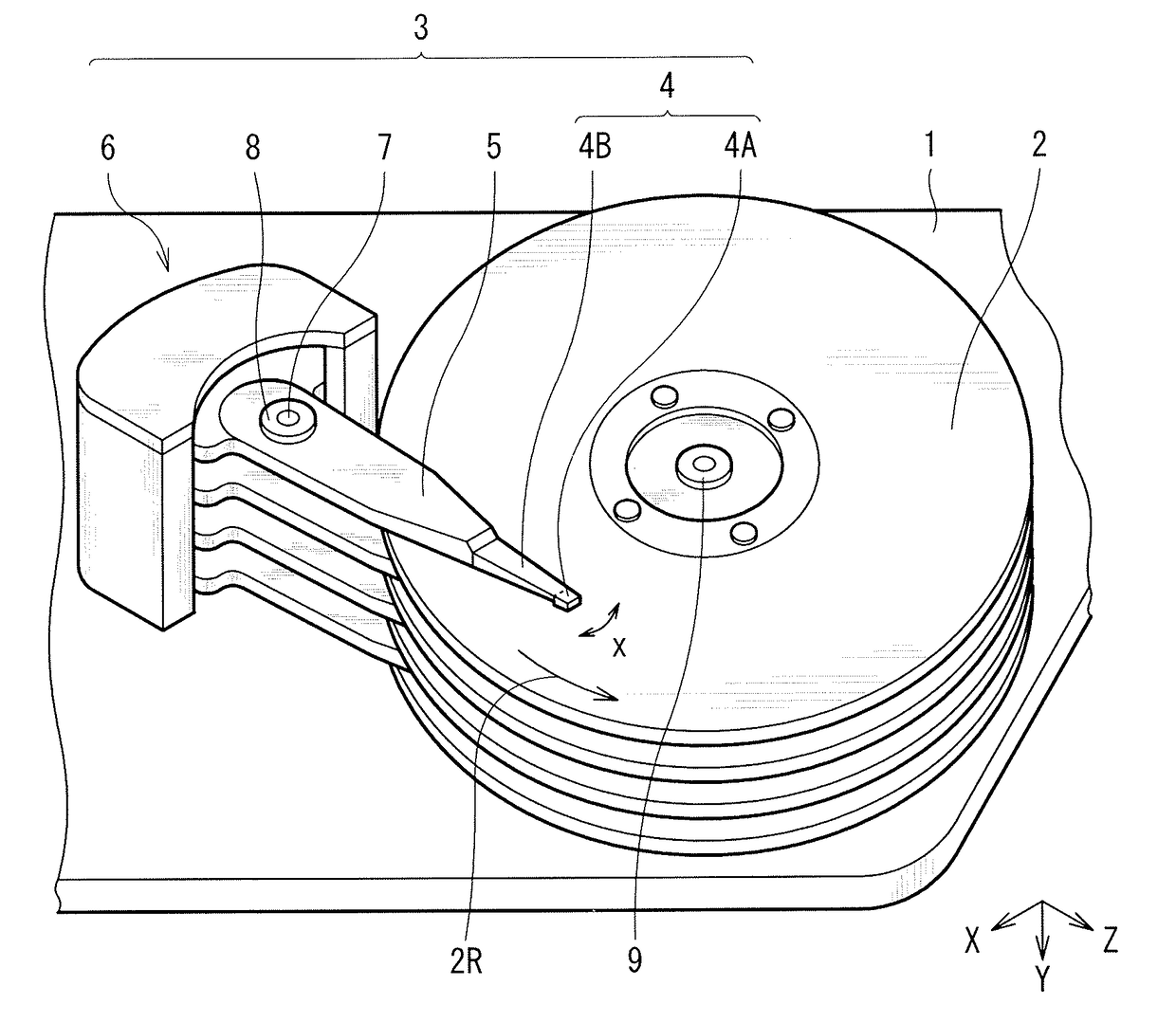
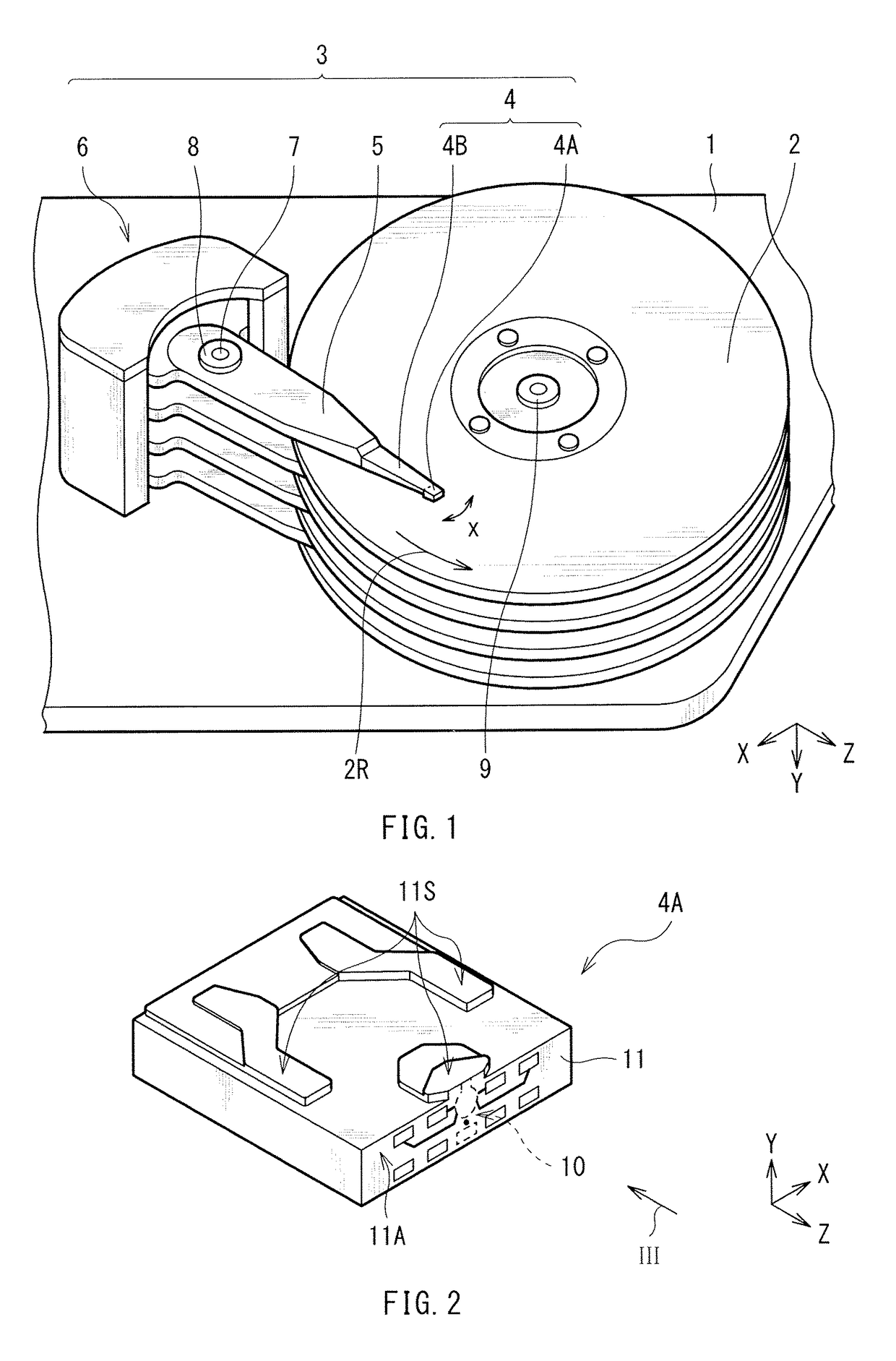
[0069]1 . . . housing, 2 . . . magnetic disk, 3 . . . head arm assembly (HAA), 4 . . . head gimbals assembly (HGA), 4A . . . slider, 4B . . . suspension, 5 . . . aim, 6 . . . driver, 7 . . . fixed shaft, 8 . . . bearing, 9 . . . spindle motor, 10 . . . thin film magnetic head, 11 . . . base, 11A . . . element forming surface, 11S . . . air bearing surface (ABS), 12 . . . ins...


PUM


Abstract

This thin film magnetic head includes a magnetic pole including an end surface exposed on an air bearing surface, and a contact detection section including a magnetic material layer provided near the air bearing surface, and a magnetic-domain stabilizing structure stabilizing a magnetic domain structure of the magnetic material layer.

Description

BACKGROUND OF THE INVENTION1. Technical Field[0001]The invention relates to a thin film magnetic head, a head gimbals assembly, a head aim assembly, and a magnetic disk unit each including a magnetic reproducing head section and a magnetic recording head section.2. Background Art[0002]Magnetic disk units have been theretofore used as a unit that records and reproduces magnetic information (hereinafter, simply referred to as information). Each of the magnetic disk units may include, for example, in a housing thereof, a magnetic disk in which information is stored, and a thin film magnetic head that records information into the magnetic disk and reproduces infoiiiiation stored in the magnetic disk. The magnetic disk is supported by a rotary shaft of a spindle motor fixed to the housing, and is configured to rotate around the rotary shaft. In contrast, the thin film magnetic head is formed on a side surface of a magnetic head slider provided on one end of a suspension, and configured t...

Claims


Application Information

Patent Timeline
IPC IPC(8): G11B5/60G11B5/48
CPCG11B5/4826G11B5/6076G11B5/314G11B5/607
Inventor KURIHARA, KATSUKIANTOKU, YOSUKETAKAHASHI, NORIO
Owner TDK CORPARATION
Why Eureka
Try Eureka