
Ratchet unit

a technology of ratcheting and straps, applied in the direction of transportation items, load transportation vehicles, vehicles, etc., can solve the problems of limiting the amount of leverage that can be applied to the strap, affecting the service life of the strap, so as to reduce the available length, increase the leverage, and provide the effect of tension

Inactive Publication Date: 2017-11-09
BREST DEREK E
View PDF0 Cites 5 Cited by
  • Summary
  • Abstract
  • Description
  • Claims
  • Application Information

AI Technical Summary

Benefits of technology

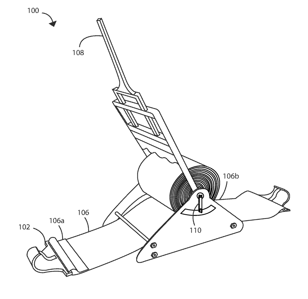
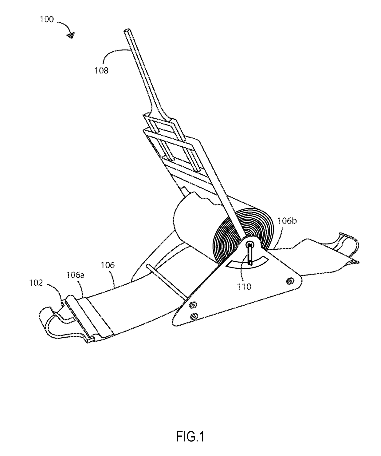
The present invention is a ratcheting unit that can be used to secure cargo and tighten straps with increased leverage, while also containing unused slack in the straps quickly for storage or while securing a load of cargo for transportation. It comprises a rotating cylinder, a ratcheting handle, and a strap of fixed length with a hook attached that can be taken up around the cylinder to provide tension. The cylinder housing has increased area around it to take up all the slack of the strap, preventing the need to fold, roll-up, or zip-tie any slack. The ratchet handle features a comfortable grip release lever and additional room for the strap. Coupled to the ratcheting cylinder is a rotating lever that can quickly take up any excess slack when the ratchet is in the open position.

Problems solved by technology

Usually, the various vehicles used for carrying goods around places face problems when carrying goods safely and conveniently while avoiding losing, dropping, slipping and breaking goods.
These ratcheting handles provide a limited range of motion and limit the amount of leverage that can be applied to the strap for securing the cargo.
Further the unused portion of the straps hang freely from the ratchet, these straps become weathered and damaged rapidly when allowed to trail freely during transportation.
Securing the slack from the unused portion of the straps prior to moving the cargo is time consuming.
In addition the hooks attached to the ends of the straps limit the anchor points they can be attached to by nature of their shape, and require extra steps or modifications in order to be used on certain vehicles before the load can be secured.

Method used


Image

  • Ratchet unit
  • Ratchet unit
  • Ratchet unit

Examples


Embodiment Construction

[0014]Reference will now be made in detail to the exemplary embodiment (s) of the invention, examples of which are illustrated in the accompanying drawings. Whenever possible, the same reference numerals will be used throughout the drawings to refer to the same or like parts.

[0015]References to “one embodiment,”“at least one embodiment,”“an embodiment,”“one example,”“an example,”“for example,” and so on indicate that the embodiment(s) or example(s) may include a particular feature, structure, characteristic, property, element, or limitation but that not every embodiment or example necessarily includes that particular feature, structure, characteristic, property, element, or limitation. Further, repeated use of the phrase “in an embodiment” does not necessarily refer to the same embodiment.

[0016]Unless defined otherwise, all technical and scientific terms used herein have the same meaning as commonly understood by one of ordinary skill in the art to which this invention belongs. Alth...


PUM


Abstract

The present invention relates to a ratcheting unit enabling for securing cargo particularly for tightness in order to secure a load of cargo quickly and safely. Typically these ratcheting straps feature a first end with one length of strap secured to the first end via a bolt, and the other length of strap is fed through a ratcheting cylinder. The ratchet allows the user to hook the straps on the distal ends to a secure anchor point, i.e. the side of a trailer. The straps are pulled taught, the loose strap is fed through the ratcheting cylinder and the ratchet handle is used to tighten the slack in the strap, bringing the strap to a higher tension than what one could easily achieve without the aid of a ratchet to hold the tension and provide leverage for taking in further slack.

Description

FIELD OF THE INVENTION[0001]The present invention relates to a ratcheting unit enabled with straps and hooks for securing cargo, particularly for tightness.BACKGROUND OF THE INVENTION[0002]Usually, the various vehicles used for carrying goods around places face problems when carrying goods safely and conveniently while avoiding losing, dropping, slipping and breaking goods. Moreover, cargo on a flatbed truck must be secured by straps for transportation, and the straps are frequently tightened by ratchet straps to prevent the items from being lost or damaged.[0003]Commonly used ratchets for securing cargo that are currently available rely on a ratcheting handle and attached spool to tighten the straps that are fed through the spool of the ratchet. These ratcheting handles provide a limited range of motion and limit the amount of leverage that can be applied to the strap for securing the cargo. Further the unused portion of the straps hang freely from the ratchet, these straps become ...

Claims


Application Information

Patent Timeline
Patent Type & Authority Applications(United States)
IPC IPC(8): B60P7/08
CPCB60P7/0853B60P7/0807B60P7/083
Inventor BREST, DEREK E.
Owner BREST DEREK E
Learn More