Door Latch System

a door latch and door latch technology, applied in the direction of passenger lock actuation, electrical locking circuit, lock application, etc., can solve the problems of complex structure and excessive maintenance cost of such door latch systems of the prior art, and achieve the effects of preventing damage to the above described components, simple structure and reducing the number of components

Active Publication Date: 2017-11-09
WOOBO TECH
View PDF5 Cites 12 Cited by
  • Summary
  • Abstract
  • Description
  • Claims
  • Application Information

AI Technical Summary

Benefits of technology

[0034]As described above, according to a door latch system of the present invention, there are advantageous effects as follows.
[0035]Since only the sub-locking member is being slid by the connecting means comprising a hook and a stopping threshold even if the door lever is being pulled when the door is being locked, the unnecessary force is not transferred to the other components such as a latch, a main locking member, and the like, therefore, damages in the above described components can be prevented.
[0036]The structure is simple since the hook can be pivotally rotated by the locking plate slidingly installed.
[0037]Since the locking plate can be moved towards t

Problems solved by technology

However, such door latch system of the prior art has a problem wherein an un-necessary force is applied to the various components such as a latch connected to the door lever and the like when the door lever is pulled while the door is being l

Method used


Image

  • Door Latch System
  • Door Latch System
  • Door Latch System

Examples


embodiment 1

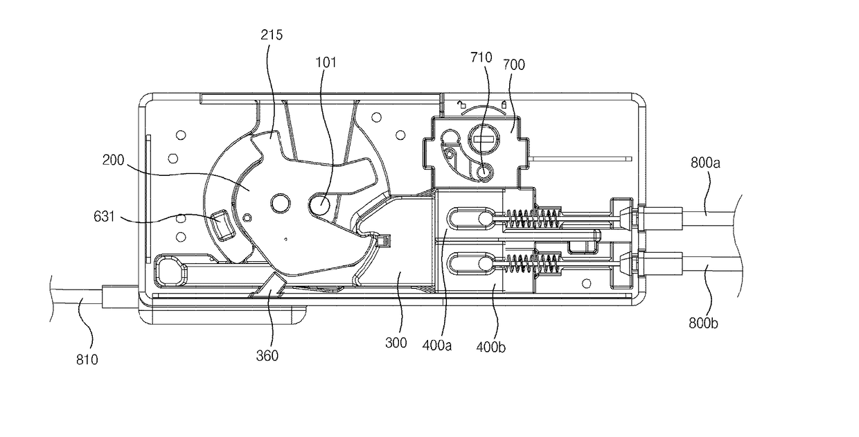
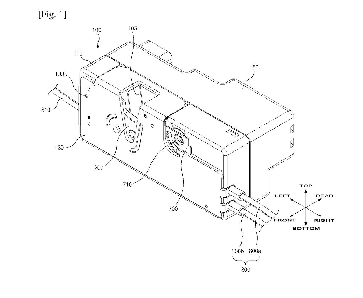
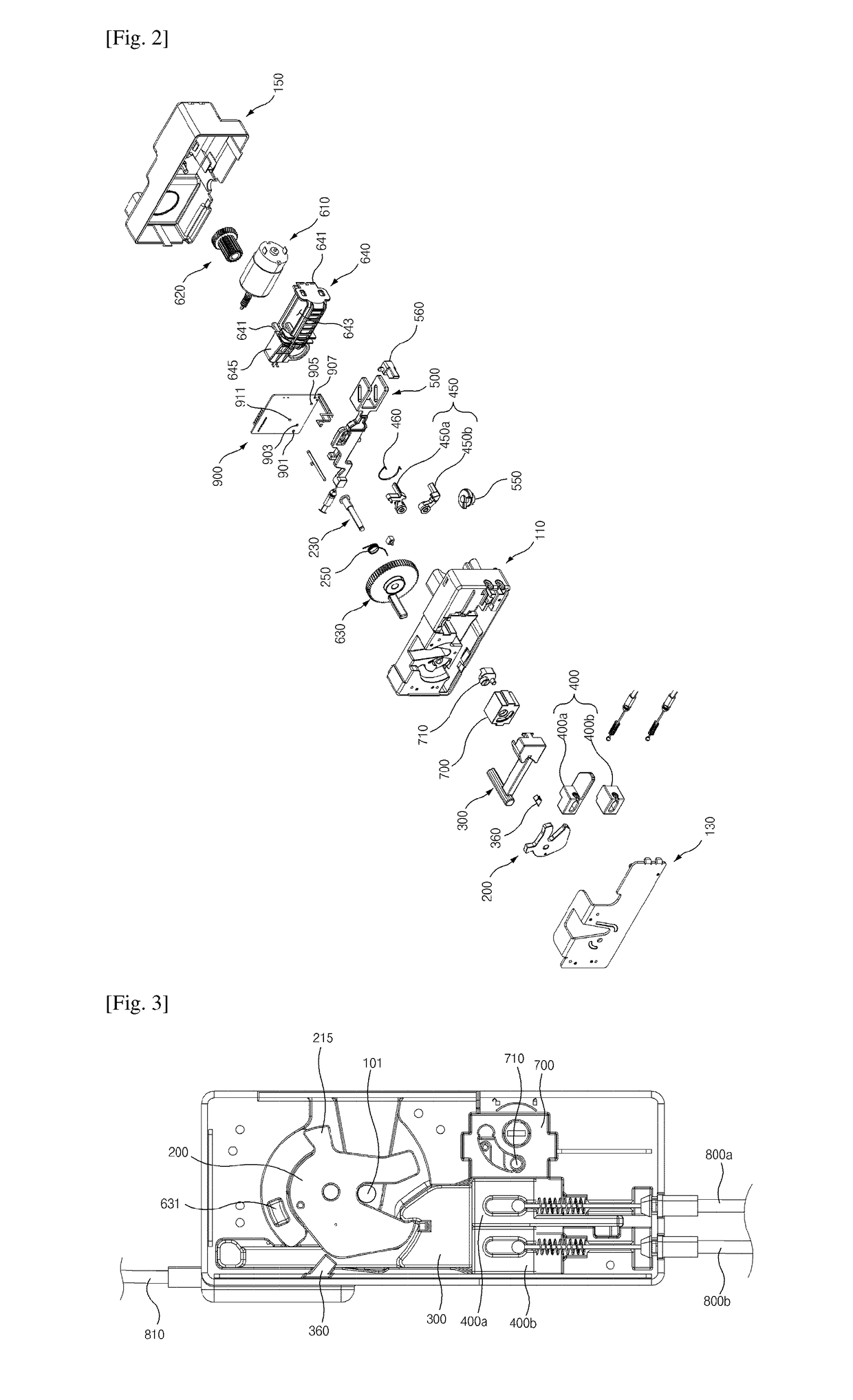
[0173]As illustrated in FIGS. 1 to 33, the door latch system according to the first exemplary embodiment of the present invention includes: a housing 100; a latch 200 pivotally and rotatably installed in the housing 100; a main locking member 300 slidingly installed in the housing 100 for locking the latch 200; a sub-locking member 400 slidingly installed in the housing 100 and disposed in one side of the main locking member 300; and a connecting means which enables simultaneous sliding of the main locking member 300 and the sub-locking member 400, or sliding of only the sub-locking member 400.

[0174]As illustrated in FIGS. 1 to 13, the housing 100 includes: a first housing 110, a second housing 130 disposed in front of the first housing 110, and the third housing 150 disposed in the backside of the first housing 110.

[0175]As illustrated in FIG. 1, in the housing 100, the front means the direction towards the second housing 130, and the backside means direction towards the third hous...

embodiment 2

[0464]In describing the door latch system according to the second exemplary embodiment of the present invention, same symbols will be used for the same or the similar elements as those of the door latch system according to the first exemplary embodiment of the present invention, and the detailed description and illustration will be omitted.

[0465]As illustrated in FIGS. 34 to 40, the door latch system according to the second exemplary embodiment of the present invention further includes a rotating member 370 for sliding the main locking member 300′ by the latch 200.

[0466]Since only the body 310′ of the main locking member 300′ is formed in a different form than that of the first exemplary embodiment of the present invention, only the body 310′ will be described and the description about the other identical configurations will be omitted.

[0467]The body 310′ constitutes the right portion of the main locking member 300′.

[0468]The body 310′ comprises the first step portion 311′ and the s...

embodiment 3

[0512]As illustrated in FIGS. 41 to 72, the door latch system according to the first exemplary embodiment of the present invention is characterized in that and includes: a housing 4100; a latch 4200 pivotally and rotatably installed in the housing 4100; a main locking member 4300 slidingly installed in the housing 4100 for locking the latch 4200; and a driving unit 4600 for pivotally rotating the latch 4200, wherein the driving unit 4600 comprises a main gear 4630, and a geared portion 4632 wherein gear teeth are formed in a portion of the peripheral surface of the main gear 4630 and a non-geared portion 4643 (without gear teeth) is formed in the remaining portion of the peripheral surface thereof.

[0513]As illustrated in FIGS. 41 to 44, the housing 4100 includes a first housing 4110, a second housing 4130 disposed in front of the first housing 4100, and the third housing 4150 disposed in the backside of the first housing 4100.

[0514]A striker insertion slot 4105 is formed in the uppe...


PUM


Abstract

This invention relates to a door latch system. The door latch system includes: a housing; a latch pivotally and rotatably installed in the housing; a main locking member slidingly installed in the housing for locking the latch; a sub-locking member slidingly installed in the housing and disposed in one side of the main locking member; a hook pivotally and movably installed in any one of the main locking member and the sub-locking member; a stopping threshold formed in the other one (wherein the hook is not installed) of the main locking member and the sub-locking member; and a locking plate slidingly installed in the housing for pivotally moving the hook, wherein the main locking member and the sub-locking member are sliding together when the hook is held by the stopping threshold by the sliding of the locking plate, and only the sub-locking member is sliding when the hook is separated from the stopping threshold by the sliding of the locking plate, so that even if the door lever is being pulled when the door is being locked, the unnecessary force is not transferred to the other components such as a latch, a main locking member, and the like.

Description

TECHNICAL FIELD[0001]The present invention relates to a door latch system, more particularly, relates to a door latch system capable of preventing the latch, the main locking member, and the like from being transferred by a force even when the door lever is being pulled as long as the door is in a locked state, and capable of setting the door to a locked state or a unlocked state with a simple structure.BACKGROUND ART[0002]Generally, a door latch system is used for opening and closing the automobile's door or locking or unlocking thereof, as suggested in Korea Patent No. 0535053.[0003]However, such door latch system of the prior art has a problem wherein an un-necessary force is applied to the various components such as a latch connected to the door lever and the like when the door lever is pulled while the door is being locked, therefore, damages in the various components of the door latch system may easily occur, consequently, there is a problem of an excessive maintenance cost.[0...

Claims


Application Information

Patent Timeline
IPC IPC(8): E05B81/16E05B77/26E05B79/20E05B81/38E05B85/26E05B85/24E05B83/36E05B15/04E05B81/74E05B81/54E05B77/44E05B81/06
CPCE05B81/16E05B77/44E05B81/54E05B81/74E05B85/243E05B85/26E05B83/36E05B79/20E05B77/26E05B15/04E05Y2900/531E05Y2201/72E05Y2400/44E05B81/06E05B81/38E05B77/32E05B81/20E05B81/34E05B81/64E05B81/66
Inventor JEONG, HAE IL
Owner WOOBO TECH
Why Eureka
Try Eureka