Imaging methods and apparatuses for performing shear wave elastography imaging

a technology of elastography and imaging methods, applied in the direction of instruments, ultrasonic/sonic/infrasonic image/data processing, and reradiation, can solve the problems of weak tissue motion, the reproducibility and reliability of images and measurements may not be optimal, and achieve the effect of improving the diagnostic performan

a technology of elastography and imaging methods, applied in the direction of instruments, ultrasonic/sonic/infrasonic image/data processing, and reradiation, can solve the problems of weak tissue motion, the reproducibility and reliability of images and measurements may not be optimal, and achieve the effect of improving the diagnostic performan

US20170322308A1Active Publication Date: 2017-11-09SUPER SONIC IMAGINE

Image

  • Imaging methods and apparatuses for performing shear wave elastography imaging
  • Imaging methods and apparatuses for performing shear wave elastography imaging
  • Imaging methods and apparatuses for performing shear wave elastography imaging

Examples


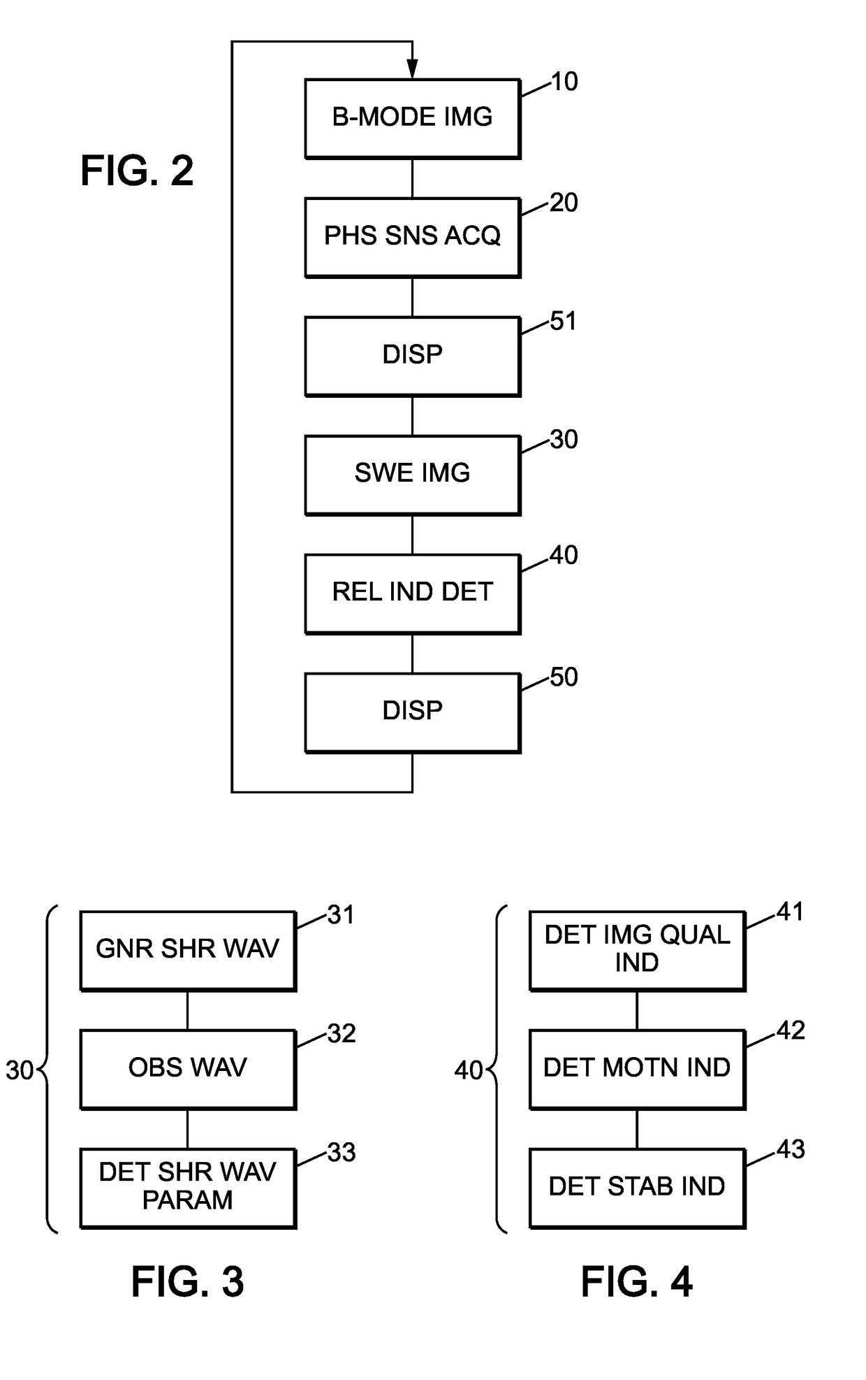
Embodiment Construction

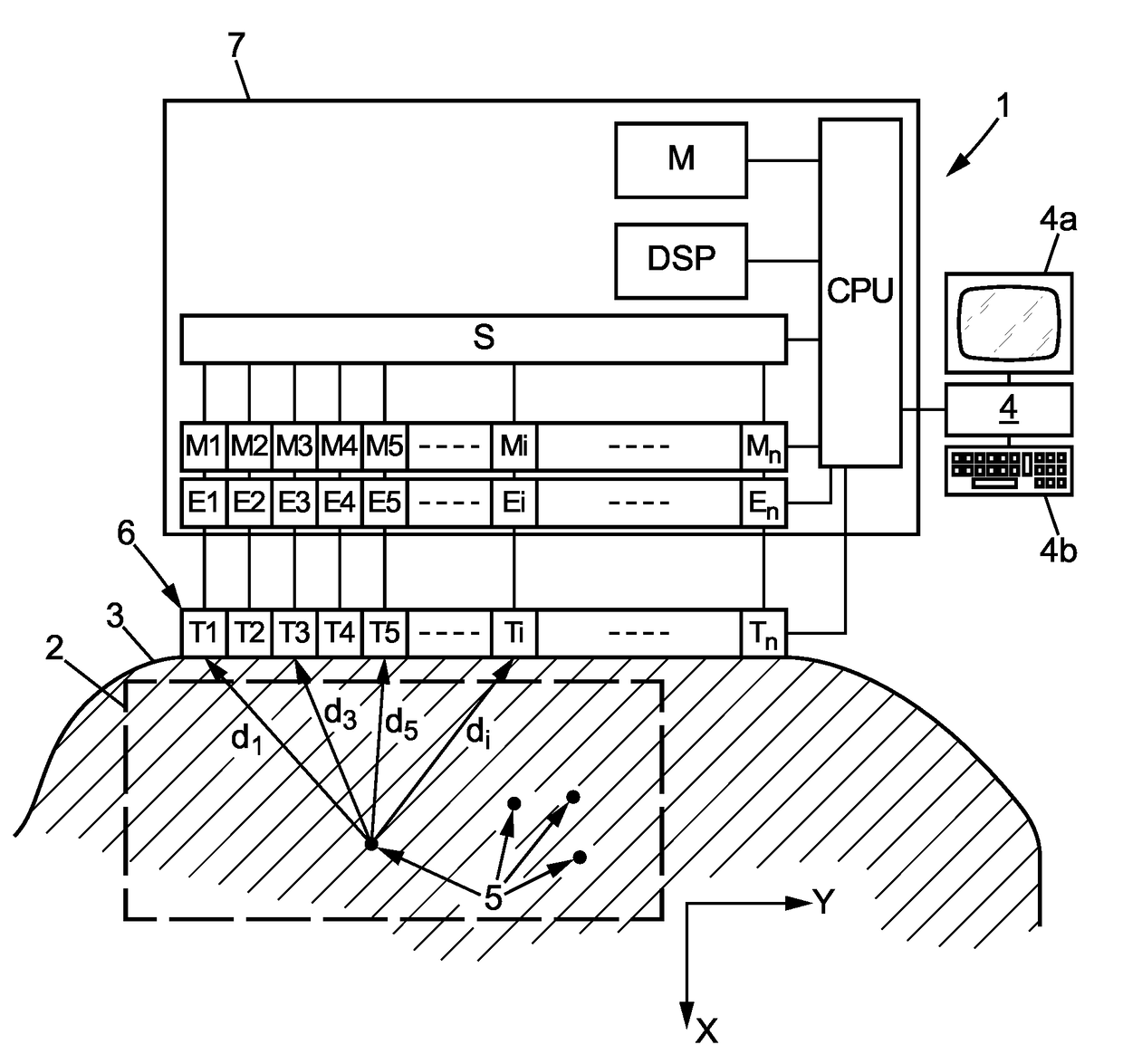
[0063]The apparatus 1 shown on FIG. 1 is an ultrasound imaging apparatus adapted for performing a shear wave elastography imaging of an observation field 2 in a medium 3, for instance imaging living tissues and in particular human tissues of a patient.

[0064]Apparatus 1 may also be able to perform conventional B-mode imaging and / or phase sensitive acquisitions such as Doppler imaging.

[0065]The apparatus 1 may include for instance:[0066]an ultrasound transducer array 6, for instance a linear array typically including a few tens of transducers (for instance 100 to 300) juxtaposed along an axis X as already known in usual echographic probes (the array 6 is then adapted to perform a bidimensional (2D) imaging of the observation field 2, but the array 6 could also be a bidimensional array adapted to perform a 3D imaging of the observation field 2);[0067]an electronic bay 7 controlling the transducer array and acquiring signals therefrom;[0068]a microcomputer 4 for controlling the electron...


PUM


Abstract

A method for performing shear wave elastography imaging of an observation field in a medium, the method including shear wave imaging steps to acquire sets of shear wave propagation parameters, the method further including a reliability indicator determining step during which a reliability indicator of the shear wave elastography imaging of the observation field is determined.

Description

FIELD OF THE INVENTION[0001]The present invention relates to imaging methods and apparatuses for performing shear wave elastography imaging of an observation field in a medium.BACKGROUND OF THE INVENTION[0002]U.S. Pat. No. 7,252,004 describes an example of a shear wave elastography method for imaging an observation field in a medium.[0003]While the method of U.S. Pat. No. 7,252,004 gives full satisfaction when tissue motion in the medium is limited, the reproducibility and reliability of images and measurements may not be optimal when tissues undergo stronger motion.[0004]For instance shear wave elastography performed in the liver and abdomen can be sensitive to small movements due to the breathing of the patient, to shadowing from the lungs ribs and intervening tissues, or even to pulsation of the organs linked to heart rate.[0005]There is thus a need for a method for performing shear wave elastography imaging of an observation field in a medium that could provide reduced measureme...

Claims


Application Information

Patent Timeline
09 Nov 2017
Publication
US20170322308A1
IPC
G01S15/89; G01S7/52; A61B8/08
CPC
G01S15/8915; G01S15/8979; A61B8/5276; A61B8/08; G01N2291/02827; A61B8/485; G01S7/52042; G01S7/52071
Inventors
LOUPAS, THANASIS; BRUCE, MATTHEW FREDERICK