Check patentability & draft patents in minutes with Patsnap Eureka AI!

Debugging support unit for microprocessor

Active Publication Date: 2017-11-09
STMICROELECTRONICS BEIJING R& D
View PDF8 Cites 10 Cited by
  • Summary
  • Abstract
  • Description
  • Claims
  • Application Information

AI Technical Summary

Benefits of technology

The patent describes a new debugging support unit that allows software developers to easily implement debugging in their programs. The unit includes a processor, communication transceiver, and a dedicated debugging register that has several registers to enable and disable different debugging operations. The debugging support unit is a hardware-based system that simplifies the debugging process and provides additional functionality. The use of the dedicated debugging support unit can improve the efficiency and ease of debugging software programs.

Problems solved by technology

The use of a conventional debugging support unit and methodologies to allow a software practitioner to debug a program has led to the discovery of significant drawbacks with the conventional approach.
Conventional debugging has heretofore been a limited and difficult to implement process.

Method used


Image

  • Debugging support unit for microprocessor
  • Debugging support unit for microprocessor
  • Debugging support unit for microprocessor

Examples


embodiment 158

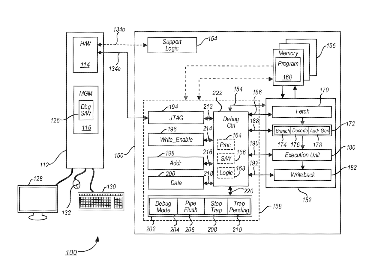
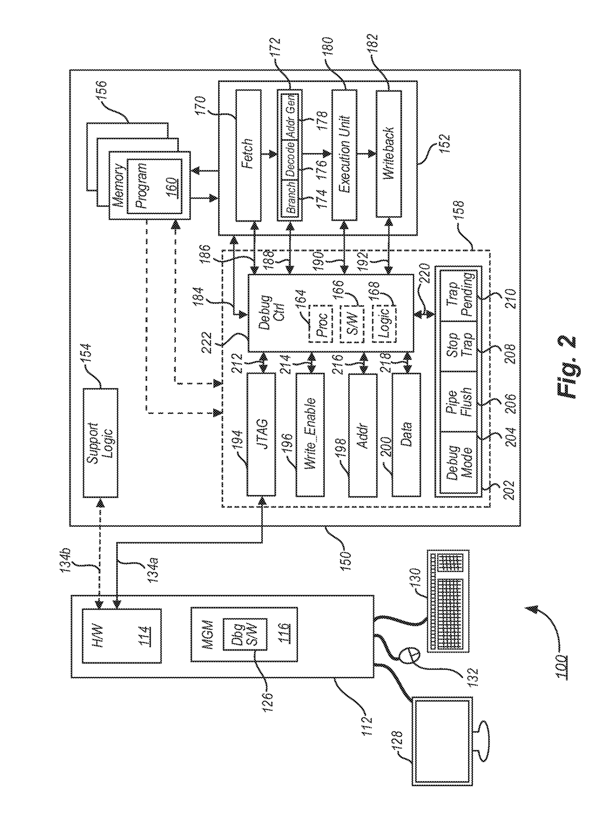
[0048]FIG. 2 is an improved debugging system 100 having an improved debugging support unit embodiment 158. The improved debugging system 100 has at least two computing devices including a host and a target. The host is a computing device 112 such as a personal computer, laptop computer, tablet, smart phone, or some other computing device; the target is a target system 150, which may be an embedded computing device directed toward a retail device, a manufacturing device, and an industrial device, a military device, a consumer device, or nearly any other kind of device that includes a processor-based system. In some cases, the target system 150 illustrated in FIG. 2 may represent the entire device, which has other features that are not shown for simplicity. For example, the target system 150 illustrated in FIG. 2 may be an industrial machine, a building system such as an air conditioning or heating unit, an automobile, or some other entire system. In other embodiments, the target syst...

embodiment 300

[0092]In the normal debugging mode, processing ends at 322. It is recognized, however, that processing in the data flow embodiment 300 may begin again at 302 at any time simply by setting the debug mode enable / disable portion 204 of the debug control register 202.

[0093]Processing in a single step debugging mode is discussed at 312. At 312, the improved DSU 158 will set the execution stop control portion 208 (i.e., StopTrap as defined in Table 2) to a first value (e.g., “1”). A particular instruction break trap, interrupt, or other user configured execution stop control will be determined to correspond with a particular instruction, which is the next instruction from where the processor 152 was stopped upon entering the debugging mode. The instruction break trap, interrupt, or user configured execution stop control, which is illustrated in FIG. 3 as “ibreak,” may be an internal register, buffer, or other repository of a particular address or indicator of a next instruction.

[0094]At 3...


PUM


Abstract

A debug-enabled processing device includes a processor, a communication transceiver circuit, and a debug support unit. The debug support unit has a plurality of dedicated debug registers to facilitate debugging a software program under execution by the processor. One of the plurality of debug registers is a control register having at least four bits, which are used to enable / disable a plurality of debugging operations. Others of the debug registers include a set of index registers that may be configured to pass data to and from the processor.

Description

BACKGROUNDTechnical Field[0001]The present disclosure generally relates to debugging a software program. More particularly, but not exclusively, the present disclosure relates to a hardware-based debugging support unit useful for debugging the software program.Description of the Related Art[0002]Ever since developers have been writing software code, there has been a need to debug software. In some cases, when software does not work properly, a developer studies the software code and tries to debug the problem mentally. In many cases, particularly when the software is more than a short simple program, a mental approach to debugging software will not work.[0003]Various tools have been created to assist developers to debug software. In some cases, the conventional debugging tools are formed entirely from software. In other cases, the conventional debugging tools are formed from a combination of hardware and software.[0004]FIG. 1 is a conventional debugging system 10. In the system, a h...

Claims


Application Information

Patent Timeline
IPC IPC(8): G06F11/36
CPCG06F11/3648G06F11/3624G06F11/2236G06F11/3636G06F11/36G06F11/3664
Inventor JIAO, XIAO KANGZHU, PENGFEI
Owner STMICROELECTRONICS BEIJING R& D
Features
  • R&D
  • Intellectual Property
  • Life Sciences
  • Materials
  • Tech Scout
  • Unparalleled Data Quality
  • Higher Quality Content
  • 60% Fewer Hallucinations
Learn More