Rotary switch for low passive intermodulation connection

a radio frequency rotary switch and low-passive intermodulation technology, applied in the direction of capacitors with electrode distance variation, dynamo-electric relays, contacts, etc., can solve the problems of low maintenance cost, increased intermodulation, and limited reduction of passive intermodulation, so as to reduce the capacitance to ground, increase coupling capacitance, and increase the coupling capacitance

Active Publication Date: 2017-11-09
SPINNER
View PDF0 Cites 5 Cited by
  • Summary
  • Abstract
  • Description
  • Claims
  • Application Information

AI Technical Summary

Benefits of technology

[0013]In a preferred embodiment, there is at least one ridge of conductive material between adjacent stationary pads. Such a ridge may be at the bottom and / or at the top of the housing. The ridge increases isolation between the stationary pads and therefore between the ports.
[0014]Preferably, the movable pads have an arcuately shaped outer contour, which may be limited by a common circle for all movable pads. This way, the movable pads are configured to rotate in close proximity (that is, at a separation distance sufficient to cause a capacitive coupling between the corresponding components and / or to form an RF signal connection between them) to an inner contour (which may be straight or arc shaped) of the stationary pads, which further increases coupling capacitance.
[0015]In a further embodiment, at least one movable pad bridge (which may be the first and / or second pad bridge) is narrower than the least one movable pad. This may result in lower capacitance to ground as the ridges are closer to the bridge than the sidewalls.

Problems solved by technology

However, there exist mechanical limits imposed on the contact force and therefore the reduction of passive intermodulation is limited as well.
Furthermore, with wear of the contacts, the intermodulation increases.
Furthermore, the disclosed switch requires low maintenance and has an extended lifetime as compared to those of related art.
This may result in lower capacitance to ground as the ridges are closer to the bridge than the sidewalls.

Method used


Image

  • Rotary switch for low passive intermodulation connection
  • Rotary switch for low passive intermodulation connection
  • Rotary switch for low passive intermodulation connection

Examples


Embodiment Construction

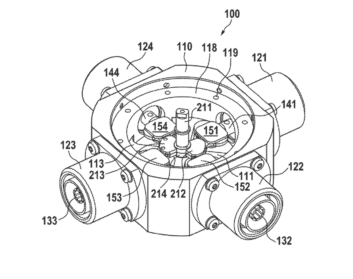
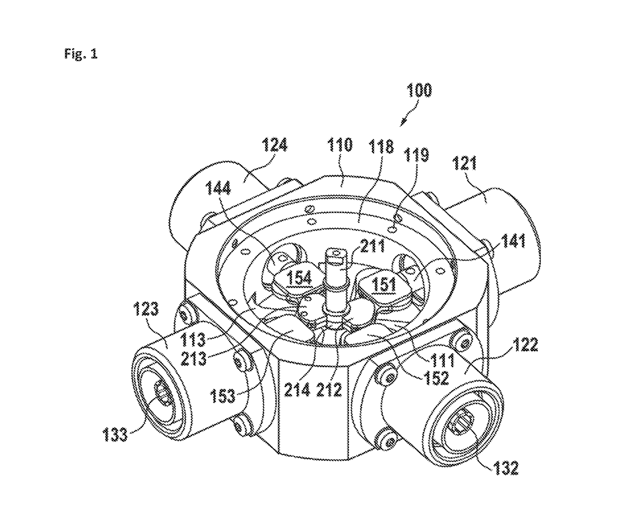
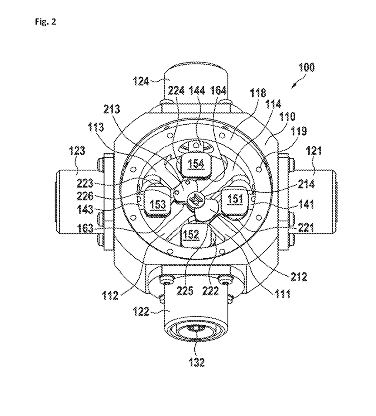
[0035]In FIG. 1, a perspective view of a preferred embodiment of a rotary switch is shown. The basic switching function is independent of the specific movement. Therefore, switches may be based on a linear or any other kind of displacement of the pads. A rotary switch 100 comprises a housing 110 for holding and enclosing the electrical components. At the housing, there are a first coaxial connector 121, a second coaxial connector 122, a third coaxial connector 123, and a fourth coaxial connector 124. For contacting, the coaxial connectors have center conductors. The first coaxial connector has a center conductor 131 (which will be shown later), the second coaxial connector has a center conductor 132, the third coaxial connector has a center conductor 133, and the fourth coaxial connector has a center conductor 134 (which will be shown later). The center conductors of the coaxial connectors are connected to respective center conductors of the switch (141, 142, 143, and 144). At the e...


PUM


Abstract

A low passive intermodulation (PIM) RF rotary switch comprises a plurality of center conductors connected to stationary pads, at least two rotatable pads being connected by a rotatable pad bridge. Depending on the switching state of the switch, at least two stationary pads are in close proximity to at least two rotatable pads, at a distance sufficient to generate/form a RF signal connection between the center conductors via the stationary and rotatable pads.

Description

CROSS-REFERENCE TO RELATED APPLICATIONS[0001]This application is a continuation from pending International Application No. PCT / EP2016 / 051025 filed on Jan. 19 2016, which designates the United States and claims priority from the European Application No. 15152379.2 filed on Jan. 23, 2015. The disclosure of each of the above-identified applications is incorporated herein by reference.BACKGROUND1. Field of the Invention[0002]The invention relates to a low passive intermodulation radio frequency rotary switch for use in switching coaxial lines. Such switches may be used in test equipment, which preferably is used for intermodulation measurement.2. Description of Relevant Art[0003]For performing tests and measurements in RF (radio frequency) equipment, it is often required to switch individual coaxial lines.[0004]U.S. Pat. No. 4,967,174 A discloses a rotating coaxial switch. This switch operates by lifting the switching circuitry before rotating. Such performance allows for increase of th...

Claims


Application Information

Patent Timeline
Patent Type & Authority Applications(United States)
IPC IPC(8): H01P1/12H01H53/02
CPCH01H53/02H01P1/125H01G5/16H01H1/2041H01H1/36
Inventor GRASSL, MARTINHUPFAUER, GEORG
Owner SPINNER
Why Eureka
Try Eureka