Systems and methods using electrical receptacles for integrated power control, communication and monitoring
Active Publication Date: 2017-11-09
BRAINWAVE RES CORP
View PDF0 Cites 30 Cited by
Summary
Abstract
Description
Claims
Application Information
AI Technical Summary
This helps you quickly interpret patents by identifying the three key elements:
Problems solved by technology
Method used
Benefits of technology
[0026]The receptacle may further include a communication subsystem for communicating with a downstream load or a second electrical receptacle that is downstream of the receptacle. Stored current fault criteria may include a threshold for the sum of current of the plug outlet and current downstream of the electrical receptacle. The processor can sample signals at the upstream plug outlet and determine that a fault,
Problems solved by technology
Conventional TR devices, however, have inherent disadvantages.
These receptacles are thus difficult to use when located close to the floor or behind an article of furniture, especially for elderly and special needs individuals.
Exposed blades prior to complete insertion or removal can result in arcing and electric shock.
Moreover, with a live load connected with the TR receptacle, an arc fault circuit interrupter (AFCI) may false trip.
An arc fault is an unintentional electrical discharge in household wiring characterized by low and erratic voltage/current conditions that may ignite combustible materials.
A parallel current fault results from direct contact of two wires of opposite polarity.
A series voltage fault occurs when there is an arc across a break in a single conductor.
Transformer current sensors are limited to a fixed current value and time interval.
The conventional devices lack capability to disconnect outlets individually, independently of other loads connected to the outlet.
Conventional circuit interrupters trip frequently by false triggers, as they lack adequate capability to distinguish between normal arcing and unwanted arcing.
Transformer current sensors are limited to a fixed current value and time interval.
The conventional devices lack capability to disconnect outlets individually, independently of other loads connected to the outlet.
Existing conventional GFCI and AFCI receptacles do not provide detail about a fault.
Existing conv
Method used
Image
Click on the blue label to locate the original text in one second.
Reading with bidirectional positioning of images and text.
Examples
Embodiment Construction
[0090]As understood in the art of electrical circuits and power lines, Black refers to hot or live power line, White refers to neutral power line, and Ground means earth ground. Last mile setups can be referred to as Black, White & Ground; or Live, Neutral and Ground. There is no potential difference (zero volts) between ground and white. The Neutral carries current back from the Black power line. Voltage Black to White potential will show the line voltage e.g., 110 V; and Ground to Black potential will show the line voltage, e.g. 110 V.
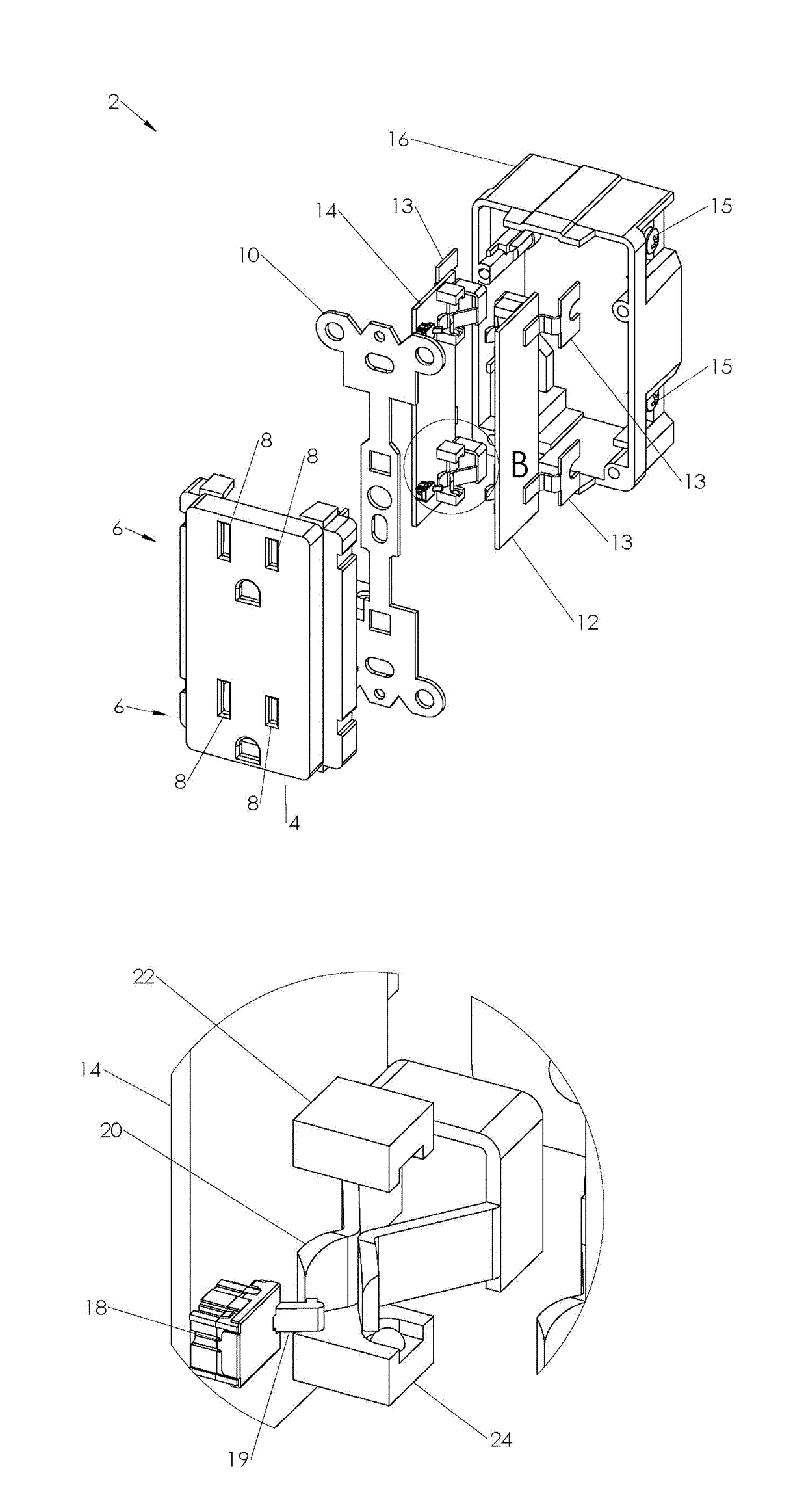
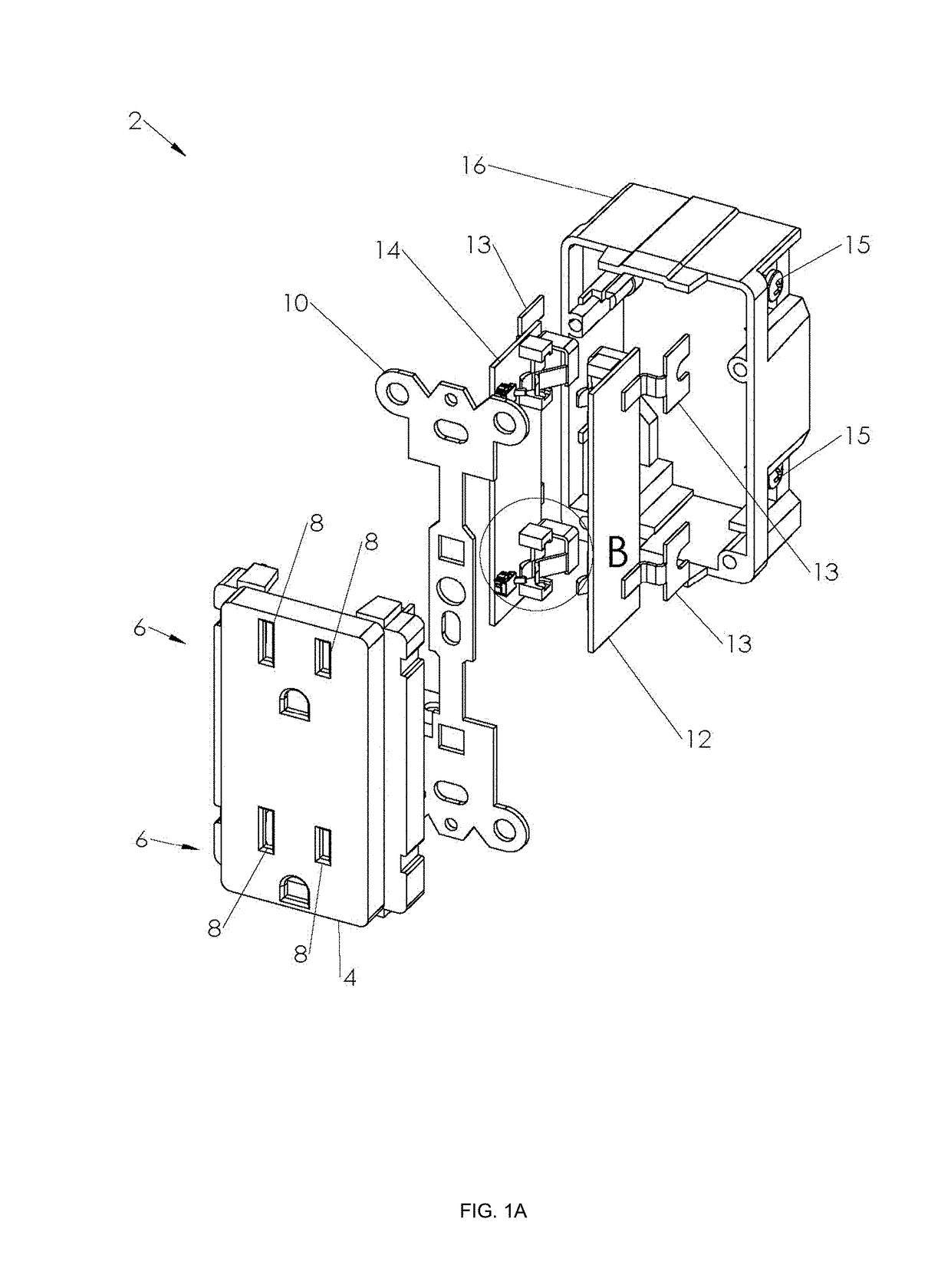
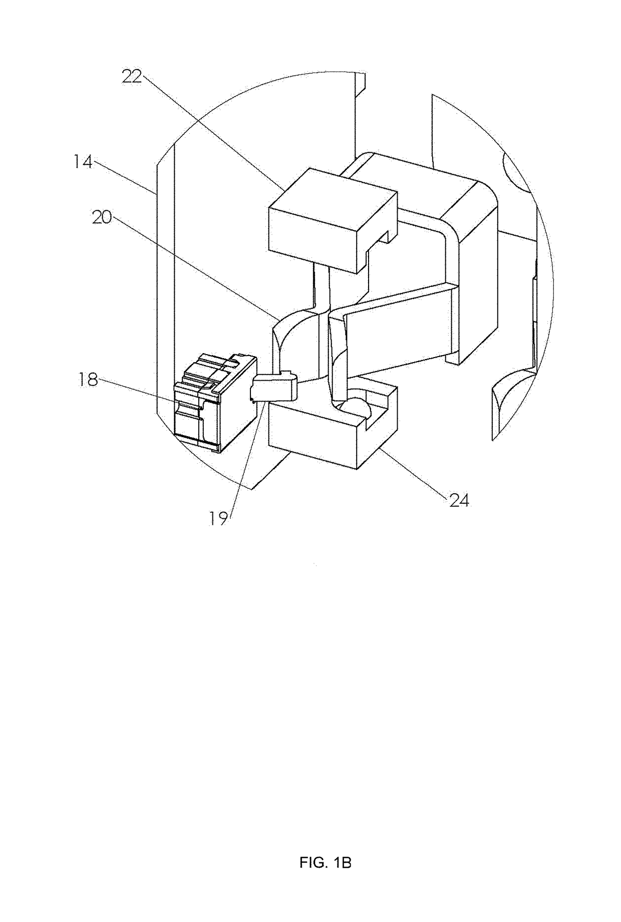
[0091]FIG. 1C is a front view of receptacle 2 without plug insertion in outlets 6. Referring to the isometric view of FIG. 1A, receptacle 2 includes front housing 4 and rear housing 16. Sockets 8 in front housing 4 serve to receive plug blades for each of two outlets 6. Enclosed within housing 4 and 16 are ground plate 10, neutral circuit board 14, hot circuit board 12 and terminal plates 13. Terminal screws 15 provide fastening to power wires. FIG. ...
PUM
Abstract
An electrical receptacle contains contacts, at least one contact for electrical connection to a hot power line and at least one contact for a neutral power line. A controlled switch, such as a TRIAC, is connected in series relationship between the contact and the hot power line. One or more sensors are provided which detect signals of the hot power line and/or the neutral power line. The processor provides activation or deactivation control to the controlled switch in response to the detected signals that are indicative of conditions relative to the first and second contacts.
Description
CROSS REFERENCE TO RELATED APPLICATIONS[0001]This application is a Continuation-In-Part of U.S. non-provisional application No. 15 / 274,469, filed Sep. 23, 2016, which claims the benefit of priority to U.S. provisional application No. 62 / 222,904, filed Sep. 24, 2015, U.S. provisional application No. 62 / 366,910, filed Jul. 26, 2016, and U.S. provisional application No. 62 / 377,962, filed Aug. 22, 2016. This application also claims the benefit of priority to U.S. provisional application No. 62 / 377,962, filed Aug. 22, 2016, U.S. provisional application No. 62 / 490,527, filed Apr. 26, 2017, and U.S. provisional application No. 62 / 505,434, filed May 12, 2017. The contents of all of these applications are herein incorporated by reference.TECHNICAL FIELD[0002]This disclosure is related to protection of electrical receptacles, more particularly, to tamper resistance, arc fault protection, ground fault protection, overcurrent protection, and surge suppression for electrical receptacles and simi...
Claims
Application Information
Patent Timeline
Application Date:The date an application was filed.
Publication Date:The date a patent or application was officially published.
First Publication Date:The earliest publication date of a patent with the same application number.
Issue Date:Publication date of the patent grant document.
PCT Entry Date:The Entry date of PCT National Phase.
Estimated Expiry Date:The statutory expiry date of a patent right according to the Patent Law, and it is the longest term of protection that the patent right can achieve without the termination of the patent right due to other reasons(Term extension factor has been taken into account ).
Invalid Date:Actual expiry date is based on effective date or publication date of legal transaction data of invalid patent.