
Acoustic baffle

a technology of acoustic baffle and acoustic cylinder, which is applied in the direction of sound producing devices, frequency/directions obtaining arrangements, instruments, etc., can solve the problems of limited space and typically large internal volume of the baffle system

Inactive Publication Date: 2017-11-09
JAGUAR LAND ROVER LTD
View PDF5 Cites 2 Cited by
  • Summary
  • Abstract
  • Description
  • Claims
  • Application Information

AI Technical Summary

Benefits of technology

The present invention relates to an acoustic baffle for attenuating sound waves generated by an acoustic source. The acoustic baffle comprises one or more cells each comprising an inlet aperture and an outlet aperture. The cells are designed to filter a predefined audio frequency or range of frequencies. The acoustic baffle can attenuate sound waves in a predetermined frequency range while facilitating the transmission of sound waves outside this range. The acoustic baffle can be used in an audio transducer and in a vehicle to reduce acoustic pressure. The invention provides an improved acoustic baffle design that can effectively attenuate sound waves and has a compact size.

Problems solved by technology

These baffle systems typically require a relatively large internal volume.
This is potentially problematic in the automotive industry where space is limited.

Method used


Image

  • Acoustic baffle
  • Acoustic baffle
  • Acoustic baffle

Examples


Embodiment Construction

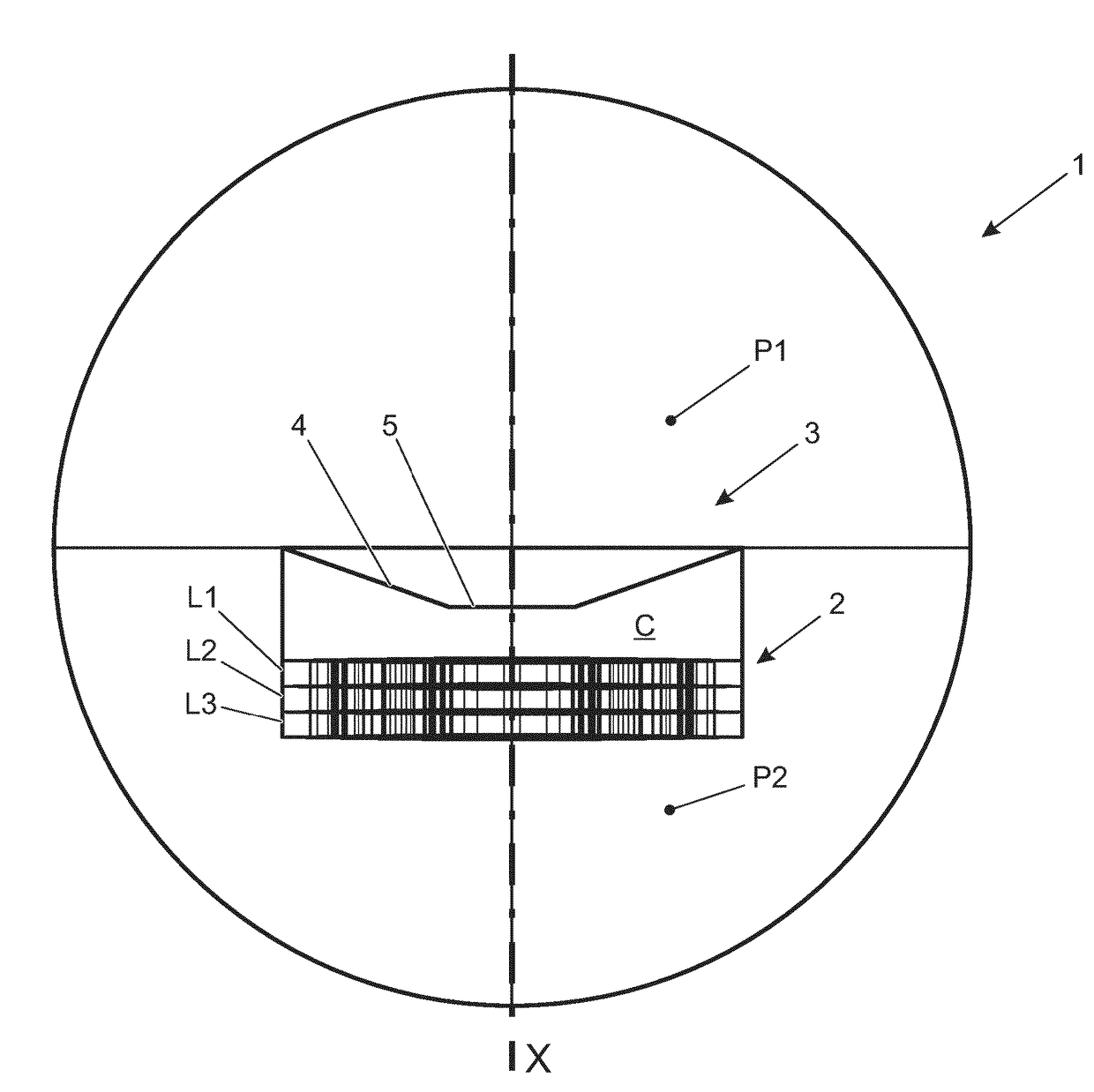
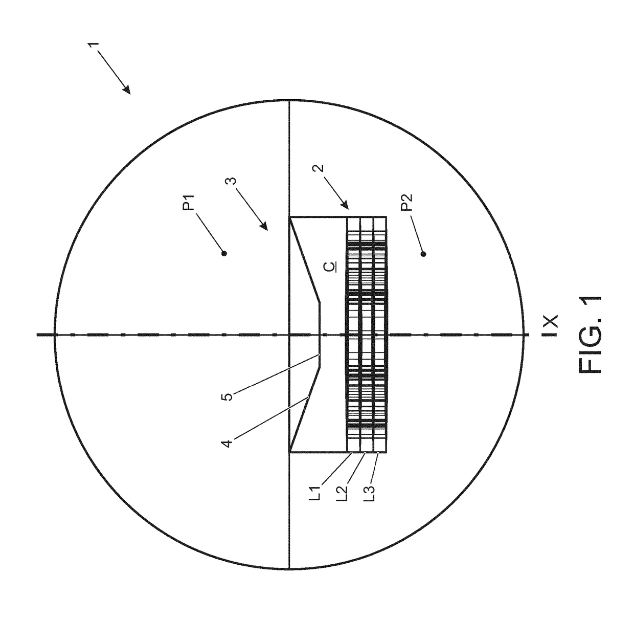
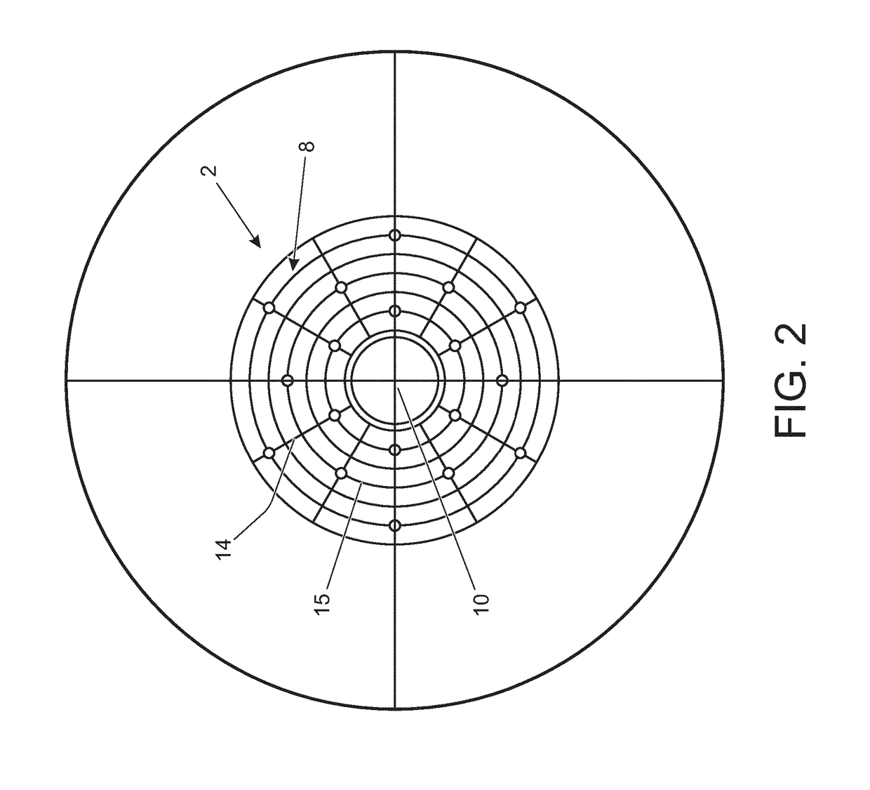
[0064]An audio transducer assembly 1 comprising an acoustic baffle 2 and an audio transducer 3 in accordance with an embodiment of the present invention will now be described with reference to the accompanying Figures. The acoustic baffle 2 in the present embodiment is configured to attenuate sound waves in the frequency range 20 Hz to 1 kHz. The audio transducer assembly 1 has particular application in an automotive vehicle, for example forming part of an audio system to generate sound waves within an occupant compartment of the vehicle.

[0065]In the present embodiment, the audio transducer 3 is in the form of a loudspeaker having a metal casing (not shown) which supports a diaphragm 4 and a permanent magnet 5. The diaphragm 4 is cone-shaped and has an outer diameter of 150mm. The diaphragm 4 is made of a semi-rigid nylon membrane adapted to support the permanent magnet 5. In use, the permanent magnet 5 interacts with a voice coil (not shown) to cause the diaphragm 4 to vibrate ther...


PUM


Abstract

The present disclosure relates to an acoustic baffle (2) for attenuating sound waves generated by an acoustic source (3). The acoustic baffle (2) is made up of one or more cells (8). The cells (8) each have opposing first and second walls (11, 12) defining at least one resonator chamber (9) for attenuating sound waves generated by the acoustic source (3). The first wall (11) has an inlet aperture (16) for ingress of sound waves generated by the acoustic source into the resonator chamber (9); and the second wall (12) has an outlet aperture (17) for egress of attenuated sound waves from the resonator chamber (9). The present disclosure also relates to an audio transducer assembly (3) including an acoustic baffle (2). Furthermore, the present disclosure relates to a vehicle including an acoustic baffle (2).

Description

TECHNICAL FIELD[0001]The present disclosure relates to an acoustic baffle, to an audio transducer assembly and to a vehicle comprising an acoustic baffle.BACKGROUND[0002]It is known to provide loudspeaker assemblies, such as woofers and subwoofers, with a baffle system to isolate out of phase acoustic signals or to reverse the phase of acoustic signals produced from the back of the audio transducer. These baffle systems typically require a relatively large internal volume. This is potentially problematic in the automotive industry where space is limited.[0003]It is against this backdrop that the present invention has been conceived. At least in certain embodiments, the present invention relates to an acoustic baffle which overcomes or ameliorates at least some of the shortcomings associated with prior art baffle systems.SUMMARY OF THE INVENTION[0004]Aspects of the present invention relate to an acoustic baffle, to an audio transducer and to a vehicle comprising an acoustic baffle.[0...

Claims


Application Information

Patent Timeline
Patent Type & Authority Applications(United States)
IPC IPC(8): H04R1/28
CPCH04R1/2811H04R2499/13H04R1/2873B60R11/0217G10K11/172H04R1/2853H04R1/2807H04R1/2857
Inventor TOMAR, ASHUTOSH
Owner JAGUAR LAND ROVER LTD
Learn More