Controller and manufacturing method thereof

a manufacturing method and controller technology, applied in the direction of electrical apparatus casings/cabinets/drawers, display/control units, coupling device connections, etc., can solve the problems of increasing the number of parts, and achieve the effects of enhancing air tightness, enhancing air tightness, and improving thermal conductivity

Inactive Publication Date: 2017-11-09
MITSUBA CORP
View PDF4 Cites 2 Cited by
  • Summary
  • Abstract
  • Description
  • Claims
  • Application Information

AI Technical Summary

Benefits of technology

[0033]According to the controller described above, the primary molded portion, the electronic component, and the power device can be collectively integrated using a resin by the secondary molded portion after the electronic component and the power device are disposed at the primary molded portion which is formed with a resin and the terminal. Accordingly, airtightness inside the controller can be enhanced. Also, since airtightness is enhanced by the resin and the resin has a higher thermal conductivity than air, the heat-dissipation property can be enhanced. Also, since a fixing structure for the electronic component and the power device and a stress relaxation structure for each terminal of the electronic component and the power device are unnecessary, a separate vibration countermeasure is unnecessary. Further, since the electronic component is provided separately from the power device in the manner of being set in the primary molded portion, the electronic component can be appropriately changed according to a specification. Therefore, a controller that has an excellent waterproof property and durability and is capable of improving applicability can be obtained.
[0034]According to the method of manufacturing a controller described above, the primary molded portion, the electronic component, and the power device can be collectively integrated using a resin by the secondary molded portion after the electronic component and the power device are disposed at the primary molded portion which is formed with a resin and the terminal. Accordingly, airtightness inside the controller can be enhanced. Also, since airtightness is enhanced by the resin and the resin has higher thermal conductivity than air, a heat-dissipation property can be enhanced. Also, since a fixing structure for the electronic component and the power device and a stress relaxation structure for each terminal of the electronic component and the power device are unnecessary, a separate vibration countermeasure is unnecessary. Further, since the electronic component is provided separately from the power device and is set in the primary molded portion, a controller in which the electronic component can be appropriately changed according to a specification can be manufactured without using a complicated mold. Therefore, the controller that has an excellent waterproof property and durability and is capable of improving applicability can be easily manufactured.

Problems solved by technology

Further, if there is a space inside, a ventilation mechanism for adjusting a pressure difference between the inside and outside of the controller is also required, and thus there is a problem in that the number of parts is increased.

Method used


Image

  • Controller and manufacturing method thereof
  • Controller and manufacturing method thereof
  • Controller and manufacturing method thereof

Examples


first embodiment

(Controller)

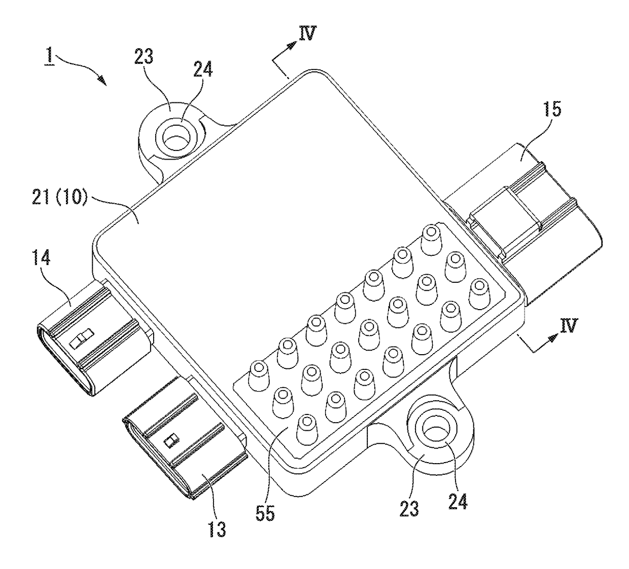
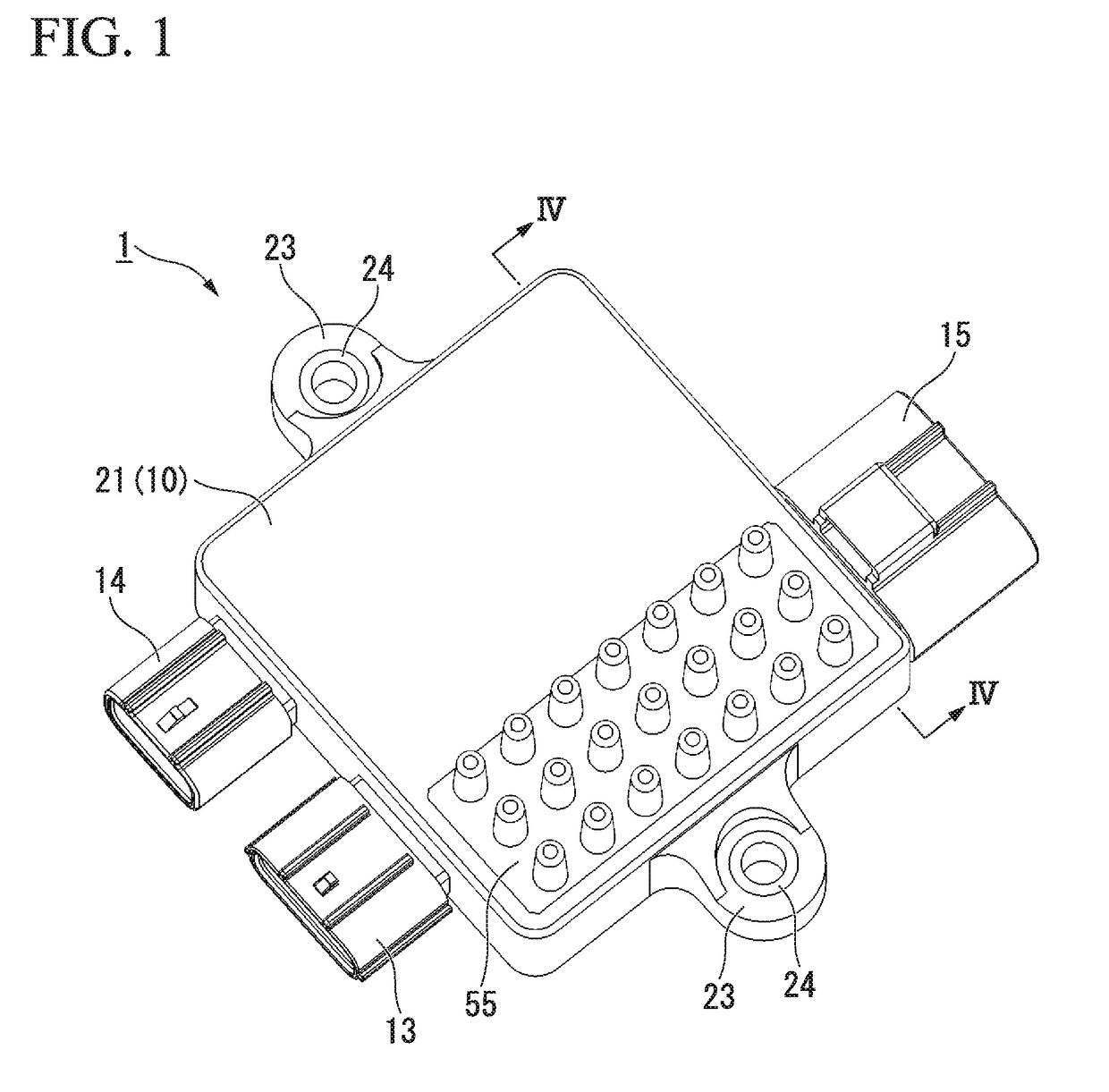
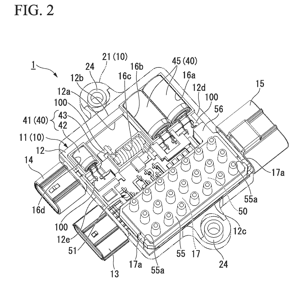
[0046]FIG. 1 is a perspective view of a controller of a first embodiment. FIG. 2 is a perspective view in which a secondary molded portion of a controller of the first embodiment is transmitted.

[0047]As shown in FIGS. 1 and 2, the controller 1 drives and controls a motor. The controller1 is attached to a motor case (a member to be attached) of the motor, for example. The controller 1 has a resin molded body 10 (a resin main body) which mainly constitutes a main body portion. A plurality of bus bars 100 (terminals), electronic components 40 connected to the bus bars 100, and a power device 50 connected to the bus bars 100 to supply power to the motor and control driving of the motor are embedded inside the resin molded body 10. Further, connector portions 13 to 15 (a first connector portion 13, a second connector portion 14, and a third connector portion 15) to which connectors (none is shown in the figure) extending from external devices can be fitted are integrally mold...

second embodiment

(Controller)

[0113]FIG. 9 is a perspective view in which a secondary molded portion of a controller of a second embodiment is transmitted. FIG. 10 is a cross-sectional view taken along line X-X of FIG. 9. Also, configurations similar to those of the first embodiment shown in FIGS. 1 to 4 will be designated by the same reference numerals and detailed description thereof will be omitted.

[0114]Here, in the first embodiment, the power device 50 and the heat sink 55 are in contact with each other via a heat-dissipation sheet (not shown). However, as shown in FIG. 10, in the second embodiment, a power device 50 and a heat sink 55 are in contact with each other via a secondary molded portion 221. This point is different from the first embodiment described above.

[0115]More specifically, as shown in FIGS. 9 and 10, the secondary molded portion 221 of a controller 201 is formed of a thermally conductive resin. It is preferable that the thermally conductive resin have excellent insulation and h...


PUM

PropertyMeasurementUnit
thermally conductiveaaaaaaaaaa
waterproof propertyaaaaaaaaaa
stress relaxationaaaaaaaaaa

Abstract

A controller (1) includes a primary molded portion (11) in which a resin molded body (10) is integrated with a bus bar (100) using a resin, causing one end of the bus bar (100) to function as a connector terminal which protrudes into connector portions (13) to (15), and configured to form electronic component disposition portions (16a) to (16d) in which an electronic component (40) is disposed and a power device disposition portion (17) in which a power device (50) is disposed, and a secondary molded portion (21) integrated with the electronic component (40), the power device (50), and the primary molded portion (11) in a state in which the electronic component (40) is disposed at the electronic component disposition portions (16a) to (16d) and the power device (50) is disposed at the power device disposition portion (17).

Description

TECHNICAL FIELD[0001]The present invention relates to a controller and a manufacturing method thereof.[0002]Priority is claimed on Japanese Patent Application No. 2014-210620, filed Oct. 15, 2014 and Japanese Patent Application No. 2015-085326, filed Apr. 17, 2015, the content of which are incorporated herein by reference.BACKGROUND ART[0003]Generally, a controller which drives a driven electric body such as a motor includes a configuration which protects a substrate which is disposed inside the controller, an electronic component such as a noise suppression device mounted on the substrate, a semiconductor device, and the like. For example, in a controller (a circuit board unit) disclosed in Patent Document 1, a substrate is sealed using an upper case and a lower case. However, in such a configuration, a waterproof seal structure for securing waterproof property is necessary at a joint portion between the upper case and the lower case. Also, in the case of the controller configurati...

Claims


Application Information

Patent Timeline
Patent Type & Authority Applications(United States)
IPC IPC(8): H05K5/00H01R43/18H01R27/02B29C70/72H05K5/02B29D99/00B29C70/88B29C70/84H01R13/50B29L31/34
CPCH05K5/0017H01R13/50H01R43/18H01R27/02H05K5/0217B29K2995/0069B29C70/882B29C70/72B29C70/84B29L2031/3481B29D99/006H02G3/105H05K5/0034H05K5/065H01L25/072H01L25/18H01L25/50H01L25/07H01L24/00
Inventor OGANE, TAKAHIKOKOSHIO, FUMIAKIKUSUMOTO, WATARUISHII, MASAMICHIYAMADA, YOSHIHISATSURUBUCHI, IWAO
Owner MITSUBA CORP
Why Eureka
Try Eureka