Uterine manipulator

a manipulator and uterine technology, applied in the field of uterine manipulators, can solve the problems of difficult insertion of cervical cups and inflatable balloons, and achieve the effect of facilitating visualization of body lumens

Inactive Publication Date: 2017-11-16
TYCO HEALTHCARE GRP LP
View PDF0 Cites 10 Cited by
  • Summary
  • Abstract
  • Description
  • Claims
  • Application Information

AI Technical Summary

Benefits of technology

[0005]One aspect of the present disclosure is directed to a uterine manipulator including an elongated, hollow shaft having a proximal end and a distal end. The hollow shaft defines a channel and has a non-opaque distal tip. A handle is positioned on a proximal portion of the shaft and an inflatable balloon that is transitional from a deflated state to an inflated state is supported on a distal portion of the shaft. A cervical cup is also movably positioned along the shaft. The channel of the shaft is dimensioned to receive an endoscope to facilitate visualization of a body lumen through the non-opaque distal tip of the shaft.

Problems solved by technology

During placement of known uterine manipulators into the uterus, visualization of the vagina, cervix and uterus may be obscured thus rendering proper placement of the cervical cup and inflatable balloon more difficult.

Method used


Image

  • Uterine manipulator
  • Uterine manipulator
  • Uterine manipulator

Examples


Embodiment Construction

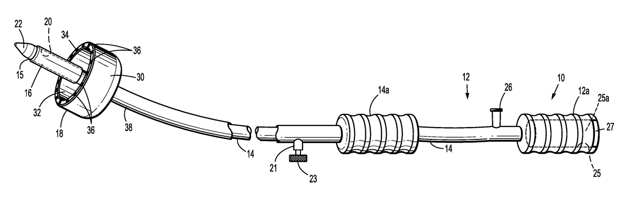
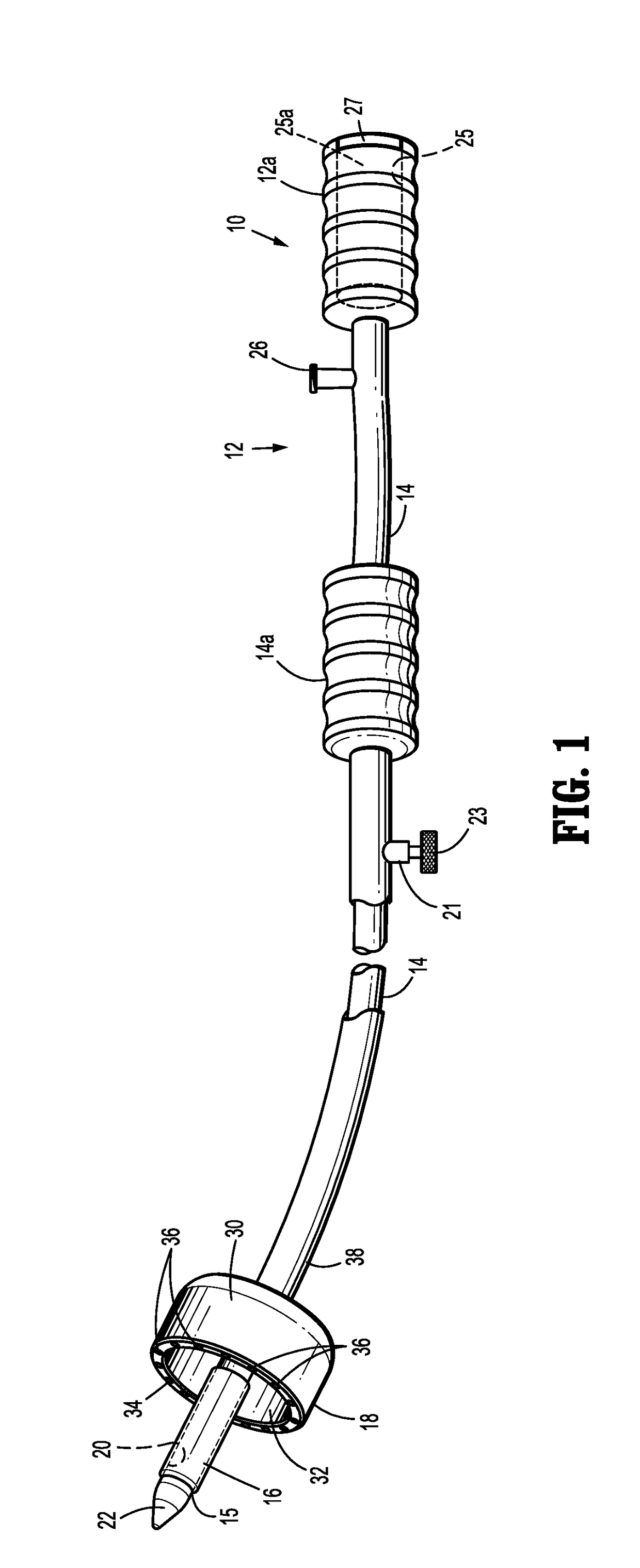
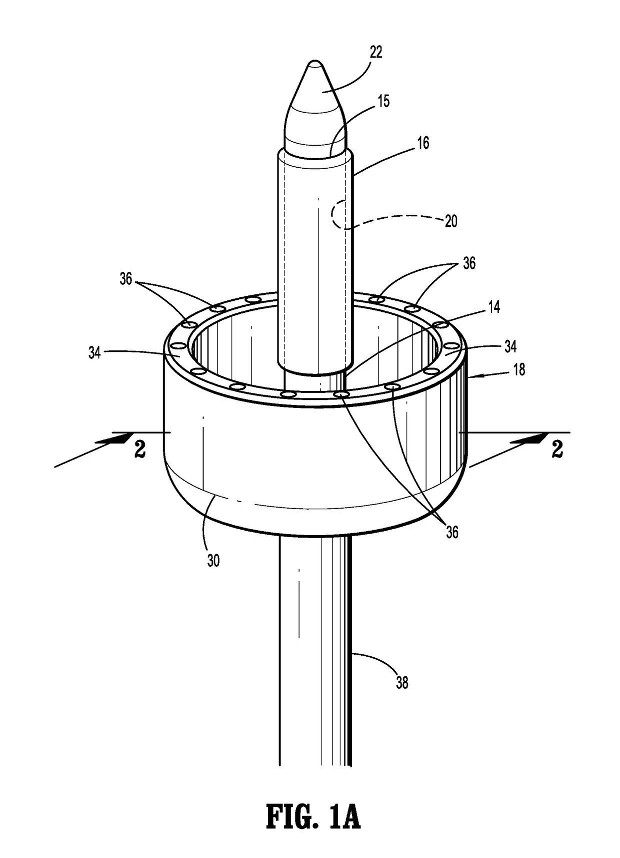
[0033]The presently disclosed uterine manipulator will now be described in detail with reference to the drawings in which like reference numerals designate identical or corresponding elements in each of the several views. In this description, the term “proximal” is used generally to refer to the portion of the apparatus that is closer to a clinician, while the term “distal” is used generally to refer to the portion of the apparatus that is farther from the clinician. In addition, the term “endoscopic” is used generally to refer to endoscopic, laparoscopic, arthroscopic, and any other surgical procedure performed through a small incision or a cannula inserted into a patient's body. Finally, the term clinician is used generally to refer to medical personnel including doctors, nurses, and support personnel.

[0034]The presently disclosed uterine manipulator is provided to improve visualization within lumens of the body as the uterine manipulator is inserted through the vagina and cervix ...


PUM


Abstract

A uterine manipulator is described that includes an elongated, hollow shaft having a proximal end and a distal end. The hollow shaft defines a channel and has a non-opaque distal tip. A handle is positioned on a proximal portion of the shaft and an inflatable balloon is supported on a distal portion of the shaft. The inflatable balloon is transitional from a deflated state to an inflated state. A cervical cup is movably positioned along the shaft from a distal position to a proximal position. The channel of the shaft is dimensioned to receive an endoscope to facilitate visualization of a body lumen through the non-opaque distal tip of the shaft. In embodiments, the cervical cup defines a rim that is positioned to abut the inflatable balloon when the cervical cup is in its distal position. The rim includes a plurality of distally facing lights that function to identify placement of the cervical cup in relation to the cervix.

Description

CROSS-REFERENCE TO RELATED APPLICATIONS[0001]This application claims the benefit of and priority to U.S. Provisional Patent Application No. 62 / 334,074 filed May 10, 2016, the entire disclosure of which is incorporated by reference herein.BACKGROUND1. Technical Description[0002]The present disclosure relates to a uterine manipulator and its method of use. More particularly, the present disclosure relates to a uterine manipulator configured to provide improved visualization during passage of the uterine manipulator through the vagina and cervix to facilitate proper placement of a distal portion of the uterine manipulator within the uterus, and its method of use.2. Background of Related Art[0003]Uterine manipulators are conventionally used during laparoscopic hysterectomies to mobilize and position the vagina and the cervix to facilitate their separation and to allow for removal of the uterus after colpotomy is performed. Typically, uterine manipulators include a handle, a shaft extend...

Claims


Application Information

Patent Timeline
Patent Type & Authority Applications(United States)
IPC IPC(8): A61B17/42A61B1/06A61B1/303A61B17/00
CPCA61B17/4241A61B17/00234A61B1/303A61B1/0676A61B1/00082A61B1/00154A61B5/065A61B5/4325A61B2017/0046A61B2017/00557A61B2090/309A61B2090/3945
Inventor PRIOR, SCOTT J.
Owner TYCO HEALTHCARE GRP LP
Why Eureka
Try Eureka