
Arm vibration damping device

a technology of vibration damping and arm, which is applied in the field of human body movement aiding devices, can solve the problems of increasing the risk of chronic disease, increasing the risk of misdiagnosis and side effects of drugs, and not having appropriate auxiliary tools to help patients, so as to reduce the influence of arm tremor, facilitate the structure arrangement of the device, and reduce the size of the entire device

Inactive Publication Date: 2017-11-16
GYENNO TECH
View PDF0 Cites 3 Cited by
  • Summary
  • Abstract
  • Description
  • Claims
  • Application Information

AI Technical Summary

Benefits of technology

The present invention provides an arm vibration damping device that has a simple structure and provides good vibration damping performance. The device reduces the influence of arm tremor by using longitudinal and transverse vibration damping modules that move fittings in a direction opposite to the tremor direction to counteract it. The U-shaped member ensures stability of the whole mounting frame and fittings during longitudinal movement. The arrangement of the main components in the device facilitates the structure arrangement and helps reduce the size of the device, facilitating hand-held use by users and improving use comfort.

Problems solved by technology

However, rapid socioeconomic development has also increased the risk of chronic disease.
Although drug treatment is dominant at present, there are also the risks of misdiagnosis and side effects of drugs.
Although it seems that physical therapy is a better way, appropriate auxiliary tools are not available to help patients to accept better treatment and persist for a long time.
In the prior art, devices for reducing arm vibration are complicated in vibration-damping structure and have poor vibration-damping performance, thus limiting the use of them.

Method used


Image

  • Arm vibration damping device
  • Arm vibration damping device
  • Arm vibration damping device

Examples


Embodiment Construction

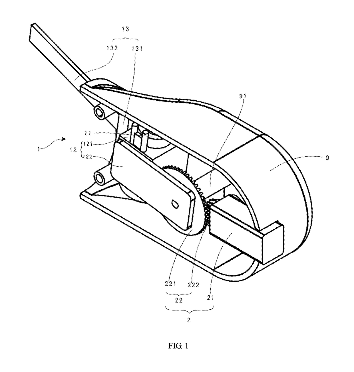
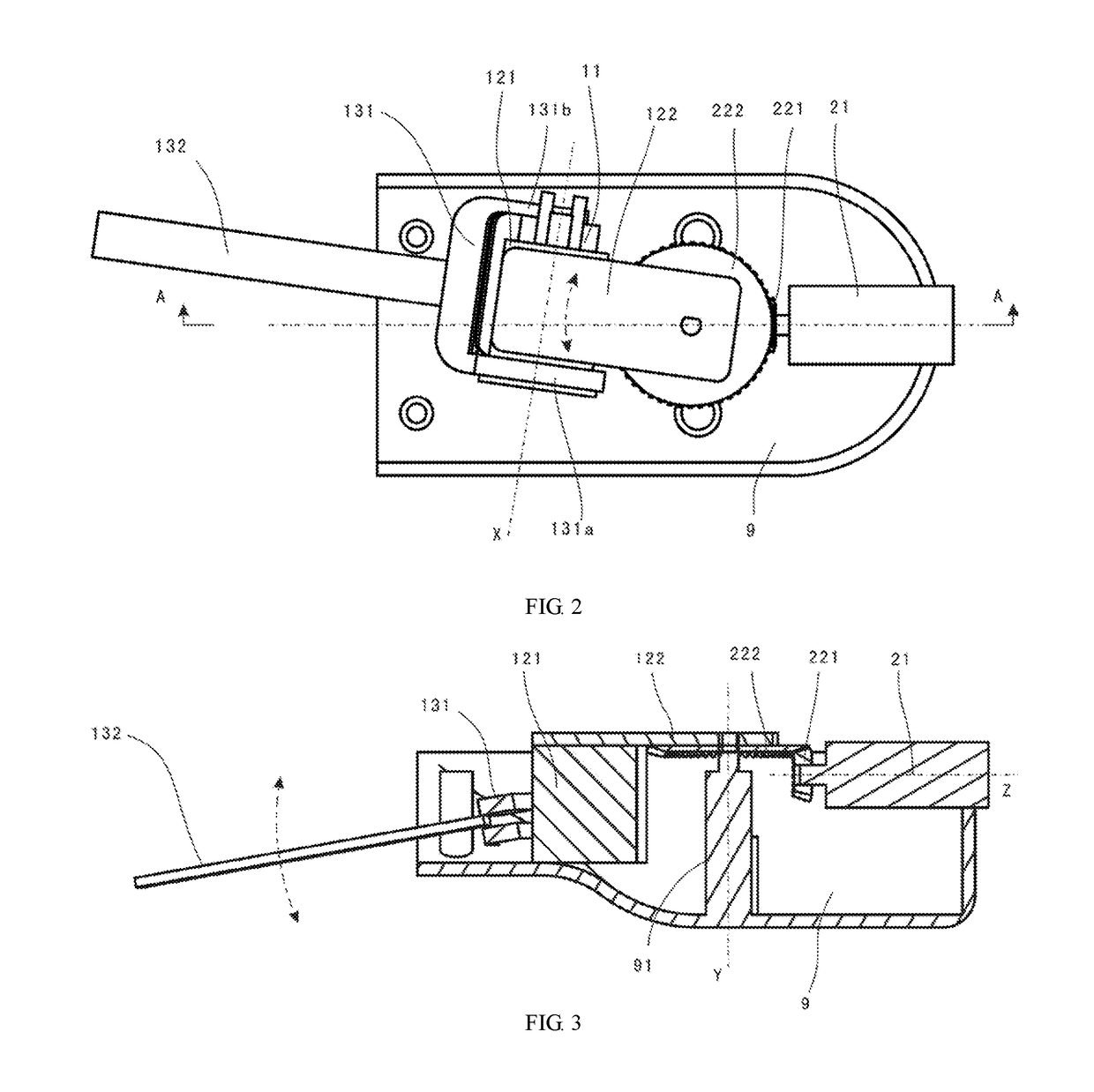
[0023]The technical solutions in embodiments of the present invention will be described clearly and completely hereinafter with reference to the accompanying drawings in the embodiments of the present invention Terms “longitudinal” and “transverse” in the embodiments are, relatively speaking, two directions. It may be understood that “longitudinal” may become “transverse” and correspondingly “transverse” may become “longitudinal” when a user changes the hand-held manner of the arm vibration damping device.

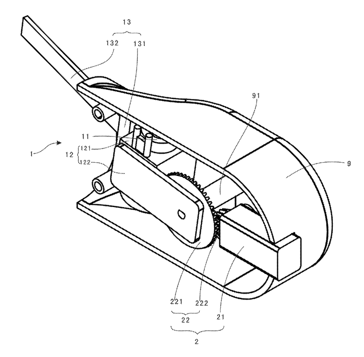
[0024]Referring to FIG. 1 to FIG. 3, the arm vibration damping device, provided by the embodiments of the present invention, comprises a housing 9, a longitudinal vibration damping module 1, and a transverse vibration damping module 2, wherein the longitudinal vibration damping module 1 and the transverse vibration damping module 2 are both arranged in the housing 9, the longitudinal vibration damping module 1 is used for drive the fittings to carry out transverse vibration damping...


PUM


Abstract

An arm vibration damping device, comprising a housing (9), a longitudinal vibration damping module (1) and a transverse vibration damping module (2), the longitudinal vibration damping module (1) comprising a longitudinal motor (11), a support frame (12) and a mounting frame (13), the mounting frame (13) comprising a U-shape element (131) and a mounting element (132); the support frame (12) being located between the U-shape element (131) and two arms, the longitudinal motor (11) being in a transmission connection with the U-shape element (131); a transverse motor (21) of the transverse vibration damping module (2) being in a transmission connection with the support frame (12) via a reverse mechanism (22); the transverse motor (21), the support frame (12), the U-shape element (131) and the mounting element (132) being arranged along an axial direction of the transverse motor (21). Vibration can be cancelled through movements in a longitudinal direction and in a direction of the longitudinal vibration damping module, and the use of two arms of the U-shape element ensures the stability of the whole mounting frame and a components fitted thereon in a longitudinal movement.

Description

TECHNICAL FIELD[0001]The present invention relates to a human body movement assisting device, and more particularly to an arm vibration damping device.BACKGROUND OF ART[0002]The industrialization and urbanization the Chinese society in rapid transformation is experiencing are rarely seen in the world in both speed and scale. However, rapid socioeconomic development has also increased the risk of chronic disease. At present, there are about 260 million people with confirmed chronic diseases in China, accounting for about 19% of the total population. The treatment of chronic diseases is divided into drug treatment and physical therapy. Although drug treatment is dominant at present, there are also the risks of misdiagnosis and side effects of drugs. Although it seems that physical therapy is a better way, appropriate auxiliary tools are not available to help patients to accept better treatment and persist for a long time.[0003]Tremor is the most common clinical symptoms of many chroni...

Claims


Application Information

Patent Timeline
Patent Type & Authority Applications(United States)
IPC IPC(8): A61H23/00A47C16/00
CPCA61H23/00A47C16/00A61H2201/5058A61H2205/06A61F5/0118A61F5/013A61F2005/0188A61F2005/0155
Inventor ZHU, YAPINGREN, KANG
Owner GYENNO TECH
Learn More