
Antenna assembly

Active Publication Date: 2017-11-16
PANASONIC AVIONICS CORP
View PDF4 Cites 12 Cited by
  • Summary
  • Abstract
  • Description
  • Claims
  • Application Information

AI Technical Summary

Benefits of technology

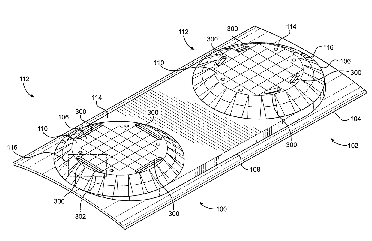
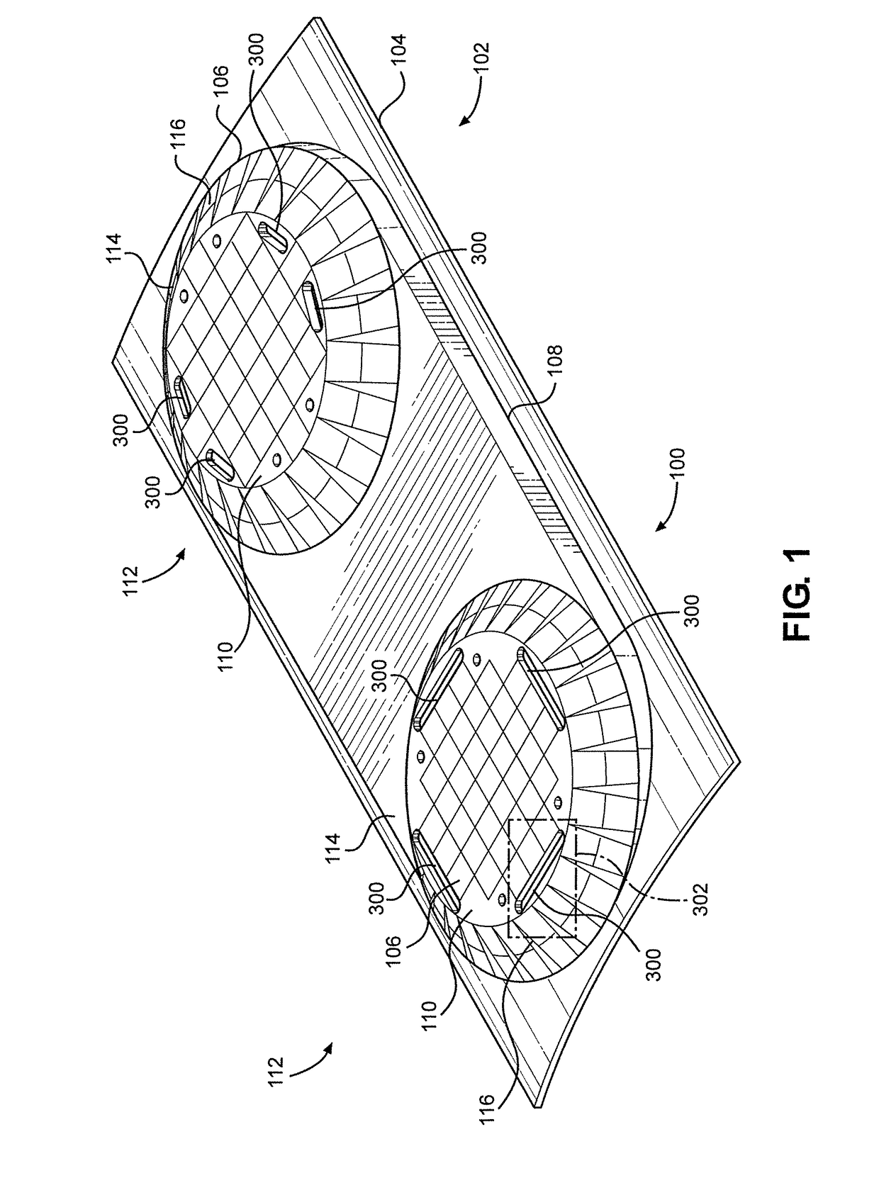
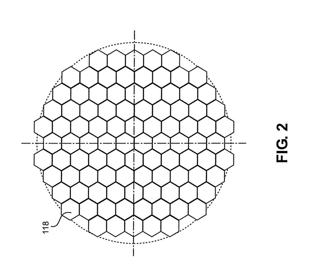
The patent describes an antenna assembly for vehicles that can support communication with a satellite. The assembly includes a support and a group of antenna tiles that form an external surface of the support. Each antenna tile has a planar array of antenna elements that can operate as a phased array. A control system is connected to the antenna elements and can selectively activate and deactivate each array. The assembly can be mounted on a vehicle in different configurations, such as an annular arrangement around a central axis or a planar arrangement. The control system can dynamically activate a subset of the tiles and align the phase and amplitude of selected antenna elements to generate a variable beam and a variable linear or circular polarization. The technical effects of the invention include improved efficiency and flexibility in satellite communication and better alignment with the satellite's line of sight.

Problems solved by technology

However, the applications have been limited to areas where the antenna can be enclosed behind a radome to reduce drag.
In addition, aircraft move at a much greater rate of speed relative to marine vessels and difficulties are frequently encountered in maintaining proper orientation of the assembly relative to a satellite, i.e., keeping the assembly pointed towards the satellite.
However, there are drawbacks, of which a major one is the limited range of angles through which the beam may be directed or steered.
While steering the beam to angles beyond this range is possible, reception and transmission performance tends to degrade rapidly.
While making the array rotatable does expand the range of angles over which nominal reception and transmission performance may be maintained, it requires the addition of mounting structure providing rotatable axes that adds significant weight.
Moreover, the mounting structure requires space for the mounting structure itself and permitting rotations of the array, which increases the profile height of the resulting antenna assembly.
Further, repeatedly rotating the planar array tends to reduce the mean time between failures (MTBF).
Finally, it requires power to operate the phased array, which results in significant waste heat that must be dissipated.
This can be difficult because the radome enclosing the antenna assembly traps heat, and excessive temperatures degrades performance of the array.
Moreover, the power required by the phased array results in increased fuel consumption.

Method used


Image

  • Antenna assembly
  • Antenna assembly
  • Antenna assembly

Examples


Embodiment Construction

[0038]As a preliminary note, the terms “component”, “module”, “system,” and the like as used herein are intended to refer to a computer-related and / or information processing entity, either software-executing general or special purpose processor, hardware, firmware and / or a combination thereof. For example, a component may be, but is not limited to being, a process running on a hardware processor, a hardware processor, an object, an executable, a thread of execution, a program, and / or a computer. For example, a controller or control system may be implemented in software, hardware, and / or a combination thereof, and may include a group of two or more control systems working cooperatively.

[0039]By way of illustration, both an application running on a server and the server can be a component. One or more components may reside within a process and / or thread of execution, and a component may be localized on one computer and / or distributed between two or more computers. Also, these componen...


PUM


Abstract

An antenna assembly including a support and antenna tiles disposed in the support. The antenna tiles form an external surface corresponding substantially in shape to lateral faces of a frustum. The frustum includes a central axis with the antenna tiles disposed around the central axis of the frustum and sloping away therefrom. Each antenna tile includes opposite ends, with one end narrower than the other end. A planar array of antenna elements is disposed on each antenna tile in which the antenna elements of each array are configured to operate as a phased array. A control system connects to the planar arrays of antenna elements in which the control system is configured to selectively activate and deactivate each of the planar arrays.

Description

CROSS-REFERENCE TO RELATED APPLICATIONS[0001]The present application is a non-provisional of prior U.S. Provisional Patent Application No. 62 / 334,548 filed May 11, 2016. The content of the foregoing prior application is hereby incorporated herein its entirety for any and all purposes.STATEMENT RE: FEDERALLY SPONSORED RESEARCH[0002]Not Applicable.TECHNICAL FIELD[0003]The present disclosure relates to antennas for satellite communication, and more particularly to antenna assemblies including an array of antenna elements configured to operate as a phased array.BACKGROUND[0004]One conventional approach to antenna assemblies for satellite communication has been to provide paraboloid shapes, i.e., a dish shape, and point it towards a satellite. This is an efficient and cost effective solution for ground based installations, especially for communication with geostationary satellites. It has also been satisfactory for some vehicle applications, such as in the maritime industry where vessels...

Claims


Application Information

Patent Timeline
IPC IPC(8): H01Q1/28H01Q21/06H01Q3/34H01Q21/22H01Q1/38
CPCH01Q1/28H01Q21/065H01Q21/22H01Q1/38H01Q3/34
Inventor LEVY, DAVIDBHATIA, BRINDERSHEMESH, YAIRSIGALOV, MICHAELENGEL, BENJAMINHABER, AMIRMARGIS, PAUL
Owner PANASONIC AVIONICS CORP
Learn More