Spark plug

a technology of spark plugs and spark plugs, which is applied in the manufacture of spark plugs, spark plugs, electrical equipment, etc., can solve the problems of reducing peeling at the tip or falling off of the tip, etc., and achieves the effect of improving the durability of ground electrodes, reducing thermal stress due to a difference in thermal expansion between the tip and the electrode base material, and ensuring the joining strength of the welded portion

Active Publication Date: 2017-11-16
NGK SPARK PLUG CO LTD
View PDF0 Cites 2 Cited by
  • Summary
  • Abstract
  • Description
  • Claims
  • Application Information

AI Technical Summary

Benefits of technology

[0007]In order to attain the above object, a spark plug according to a first aspect of the present invention includes a tip that contains a noble metal and forms a spark gap between the tip and a center electrode (i.e., positioned to form a spark gap between the tip and the center electrode). The tip is joined to a joining surface of an electrode base material (or, as used interchangeably herein, an electrode base) of a ground electrode via a welded portion. On cross-sections of the tip and the electrode base material in a longitudinal direction of the joining surface, the welded portion has a void above the joining surface, and a continuous distance of the welded portion on the joining surface is less than or equal to 0.5 mm. In other words, the tip defines one or more voids above the joining surface and between the plurality of welded portions, and the welded portions are each less than or equal to 0.5 mm in the longitudinal direction. Therefore, as compared to a case where the entirety of the interface of the tip is joined to the electrode base material, thermal stress due to a difference in thermal expansion between the tip and the electrode base material can be reduced. A total of continuous distances of the welded portions on the joining surface, are 0.4 times to 0.8 times a length from an end of the tip to another end thereof, whereby joining strength of the welded portion can be assured. As a result, peeling at the tip or falling-off of the tip due to thermal stress, vibration, or the like can be less likely to occur. Therefore, an effect of improving durability of the ground electrode can be obtained.
[0008]In the spark plug according to a second aspect of the present invention, the tip has a plurality of divisional tips arranged on the joining surface. The welded portions adjoin each of the divisional tips to the joining surface. The size of the divisional tip can be reduced as compared to an integral tip. Therefore, in addition to the effect by the first aspect being obtained, an effect of reducing thermal stress caused by a difference in thermal expansion between the tip and the electrode base material can be enhanced. Further, a maximum spatial distance, on the joining surface, between the divisional tips adjacent to each other is less than or equal to 0.3 mm. Therefore, spark discharge at the electrode base material between the divisional tips can be less likely to occur. As a result, an effect of reducing spark wear of the electrode base material between the divisional tips can be obtained.
[0009]In the spark plug according to a third aspect of the present invention, on the cross-sections of the tip and the electrode base material in the longitudinal direction of the joining surface, the length from the end of the tip to the other end thereof is greater than or equal to 1.5 mm. The greater the length of the tip is, the greater the dimensional change due to heat is, so that peeling at the tip or falling-off of the tip is likely to occur. However, a plurality of voids are formed above the joining surface at the welded portion, whereby the peeling or falling-off can be prevented. As a result, in addition to the effect by the first aspect or the second aspect being obtained, even when the tip has the length which is greater than or equal to 1.5 mm, peeling at the tip or falling-off of the tip due to thermal stress can be less likely to occur.

Problems solved by technology

However, in the technique disclosed in Patent Document 1, the tip is jointed to the electrode base material via a welded portion formed over the entirety of an interface of the tip, so that thermal stress may cause peeling at the tip or falling-off of the tip.
Therefore, a problem arises that durability of the ground electrode may be reduced.

Method used


Image

  • Spark plug
  • Spark plug
  • Spark plug

Examples


examples

[0063]The present invention will be more specifically described according to examples. However, the present invention is not limited to the examples.

experimental examples 1 to 20

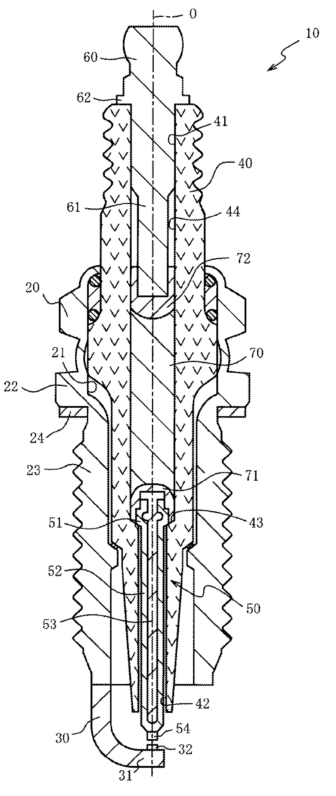
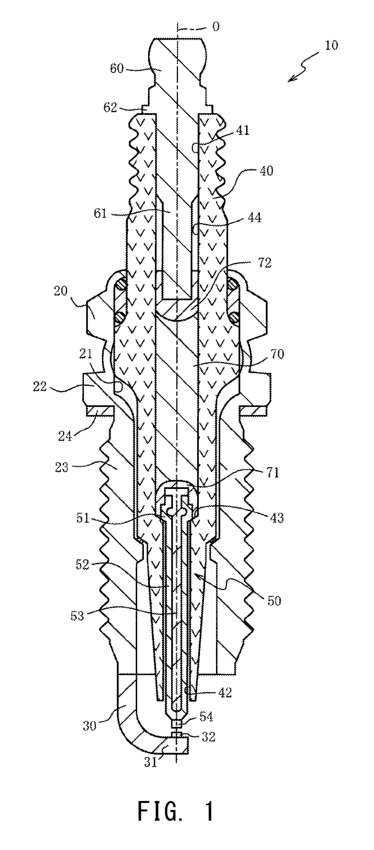
[0064]Samples according to experimental examples 1 to 20 were produced in a manner similar to that for the spark plug 10 described in the first embodiment. The samples were each a spark plug which had a screw portion of which the nominal diameter was M12. In the center electrode, a tip formed of iridium in a columnar shape having the diameter of 0.6 mm was joined to the end of the leg portion by resistance welding.

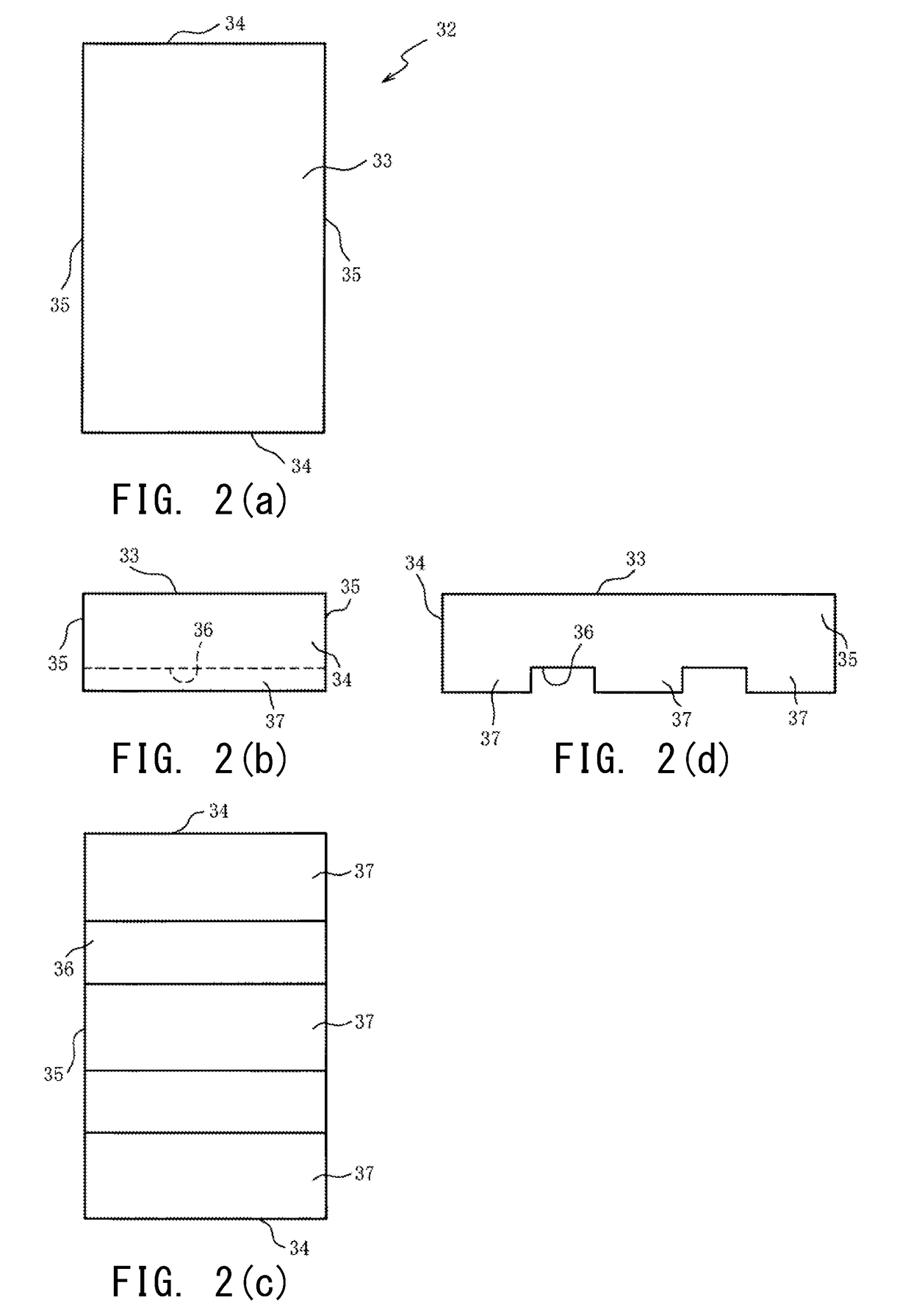
[0065]The tip of the ground electrode was formed of platinum in a rectangular parallelepiped. The tip had the width of 1 mm, the length of 1.5 mm, and the thickness of 0.4 mm. 19 kinds of tips were prepared such that grooves were formed at one to three portions on the bottom surface of the tip so as to extend in the tip width direction, and protrusions having the same length were formed parallel with each other so as to be separated by various grooves in the tips.

[0066]Each protrusion of the tip was pressed onto the electrode base material formed of INCONEL (registered tra...

experimental examples 21 to 26

[0071]The tip according to the tip of experimental example 16 was cut at positions of the grooves in the width direction, and divided into four divisional tips having the same size such that each divisional tip had the width of 1 mm, the length of 0.35 mm, and the thickness of 0.4 mm. Each divisional tip had a protrusion having the width of 1 mm and the length of 0.2 mm.

[0072]The four divisional tips were arranged on the electrode base material formed of INCONEL (registered trademark) 600 such that the protrusions were parallel to each other, and the protrusions were pressed onto the electrode base material, and the divisional tips were joined to the electrode base material by resistance welding. When the divisional tips were arranged on the electrode base material, the maximum spatial distance (gap) between the divisional tips adjacent to each other was made different, to obtain samples according to experimental examples 21 to 26. In each sample, a 0.2 mm gap was formed between the...


PUM

PropertyMeasurementUnit
distanceaaaaaaaaaa
spatial distanceaaaaaaaaaa
lengthaaaaaaaaaa

Abstract

A tip that contains a noble metal is joined to a joining surface of an electrode base material of a ground electrode via a welded portion. On cross-sections of the tip and the electrode base material in a longitudinal direction of the joining surface, the welded portion has a void above the joining surface, and a continuous distance of the welded portion on the joining surface is less than or equal to 0.5 mm, whereby thermal stress due to a difference in thermal expansion between the tip and the electrode base material can be reduced. A total of continuous distances of the welded portions on the joining surface, are 0.4 times to 0.8 times a length from an end of the tip to another end thereof, whereby joining strength of the welded portion can be assured. Peeling at the tip or falling-off of the tip due to thermal stress can be less likely to occur, whereby durability of the ground electrode can be improved.

Description

CROSS REFERENCE TO RELATED APPLICATION[0001]The present application claims priority to Japanese Patent Application No. 2016-094220, which was filed on May 10, 2016, the disclosure of which is herein incorporated by reference in its entirety.BACKGROUND OF THE INVENTIONField of the Invention[0002]The present invention relates to a spark plug, and particularly to a spark plug that allows improvement of durability of a ground electrode.Description of Related Art[0003]A spark plug in which a tip containing a noble metal is joined to an electrode base material of a ground electrode, in order to improve spark wear resistance of the ground electrode, is known (Patent Document 1).PRIOR ART DOCUMENT[0004]Patent Document 1 is Japanese Patent Application Laid-Open (kokai) No. 2003-217792.SUMMARY OF THE INVENTION[0005]However, in the technique disclosed in Patent Document 1, the tip is jointed to the electrode base material via a welded portion formed over the entirety of an interface of the tip...

Claims


Application Information

Patent Timeline
Patent Type & Authority Applications(United States)
IPC IPC(8): H01T13/32H01T13/39H01T13/41
CPCH01T13/32H01T13/39H01T13/41H01T21/02H01T13/20
Inventor YAMADA, YUICHIMATSUNAGA, YUICHI
Owner NGK SPARK PLUG CO LTD
Why Eureka
Try Eureka