Smooth Pitch Control for Propellers and Rotors
- Summary
- Abstract
- Description
- Claims
- Application Information
AI Technical Summary
Benefits of technology
Problems solved by technology
Method used
Image

Examples
Embodiment Construction
[0020]FIGS. 1 and 3 are typical torque vs. deflection curves for rolling-element and elastomeric bearings, respectively. FIG. 1 illustrates the instantaneous change in friction torque experienced by a rolling-element thrust bearing under high load conditions. FIG. 3 instead shows the smooth incremental change in torque experienced by an elastomeric bearing under the same conditions.
[0021]FIG. 2 represents the basic construction and function of an elastomeric thrust bearing 1. Laminated rubber or elastomeric bearings comprise a stack of many thin alternate layers of metal 2 (white) and rubber 3 (black) bonded together to form a solid mass. It may have a central aperture as shown. The bearing yields to partial rotation, which depends upon incremental movements between each of the metal layers via sideways shearing action within the intervening rubber layers. The illustration depicts the partial rotation of the top of the bearing, showing movement of a line that is vertical when drawn ...
PUM
 Abstract
Description
Claims
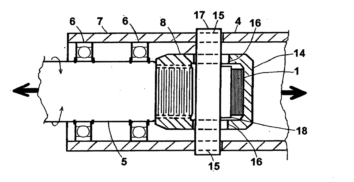
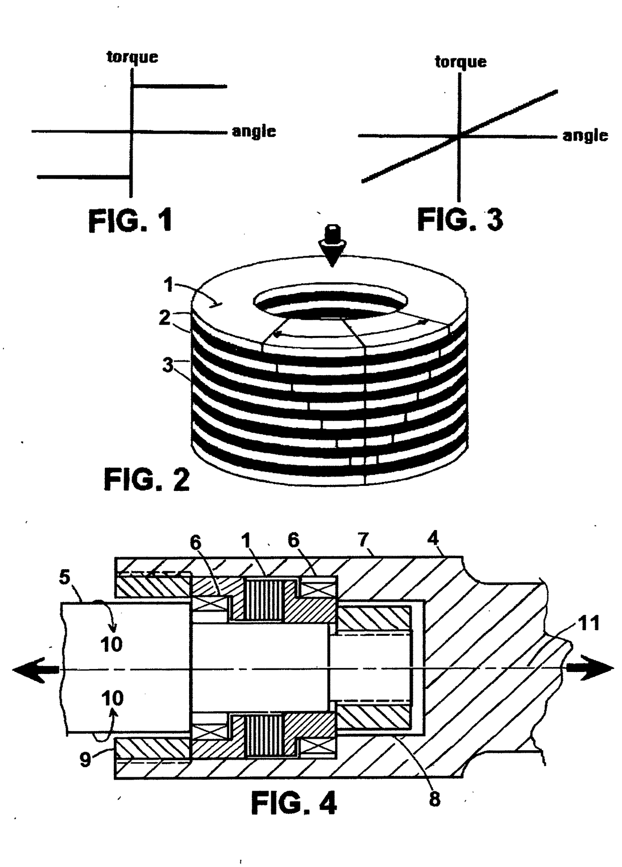
Application Information
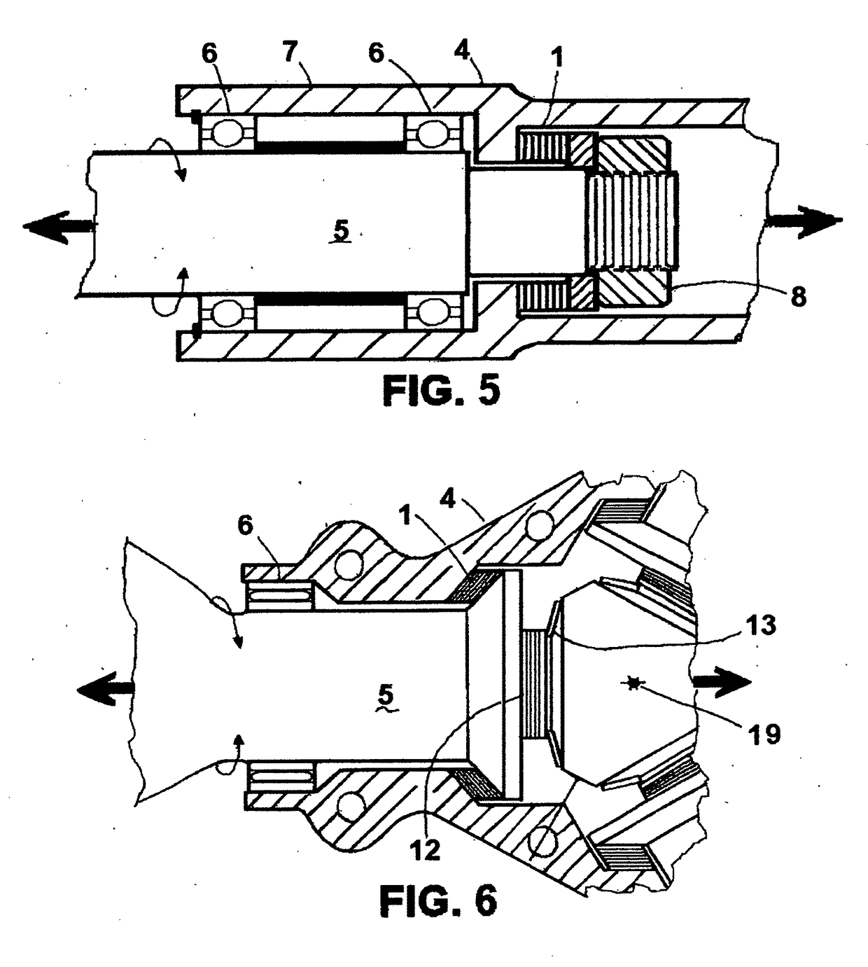
 - Generate Ideas
- Intellectual Property
- Life Sciences
- Materials
- Tech Scout
- Unparalleled Data Quality
- Higher Quality Content
- 60% Fewer Hallucinations
Browse by: Latest US Patents, China's latest patents, Technical Efficacy Thesaurus, Application Domain, Technology Topic, Popular Technical Reports.
© 2025 PatSnap. All rights reserved.Legal|Privacy policy|Modern Slavery Act Transparency Statement|Sitemap|About US| Contact US: help@patsnap.com