This helps you quickly interpret patents by identifying the three key elements:
Problems solved by technology
Method used
Benefits of technology
Benefits of technology
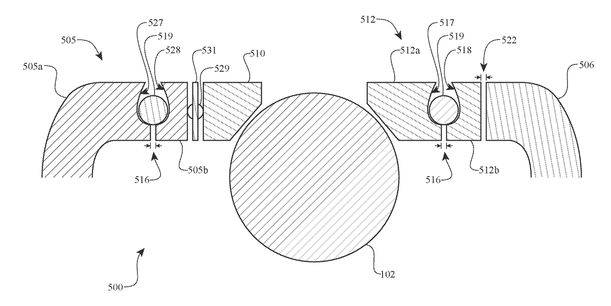
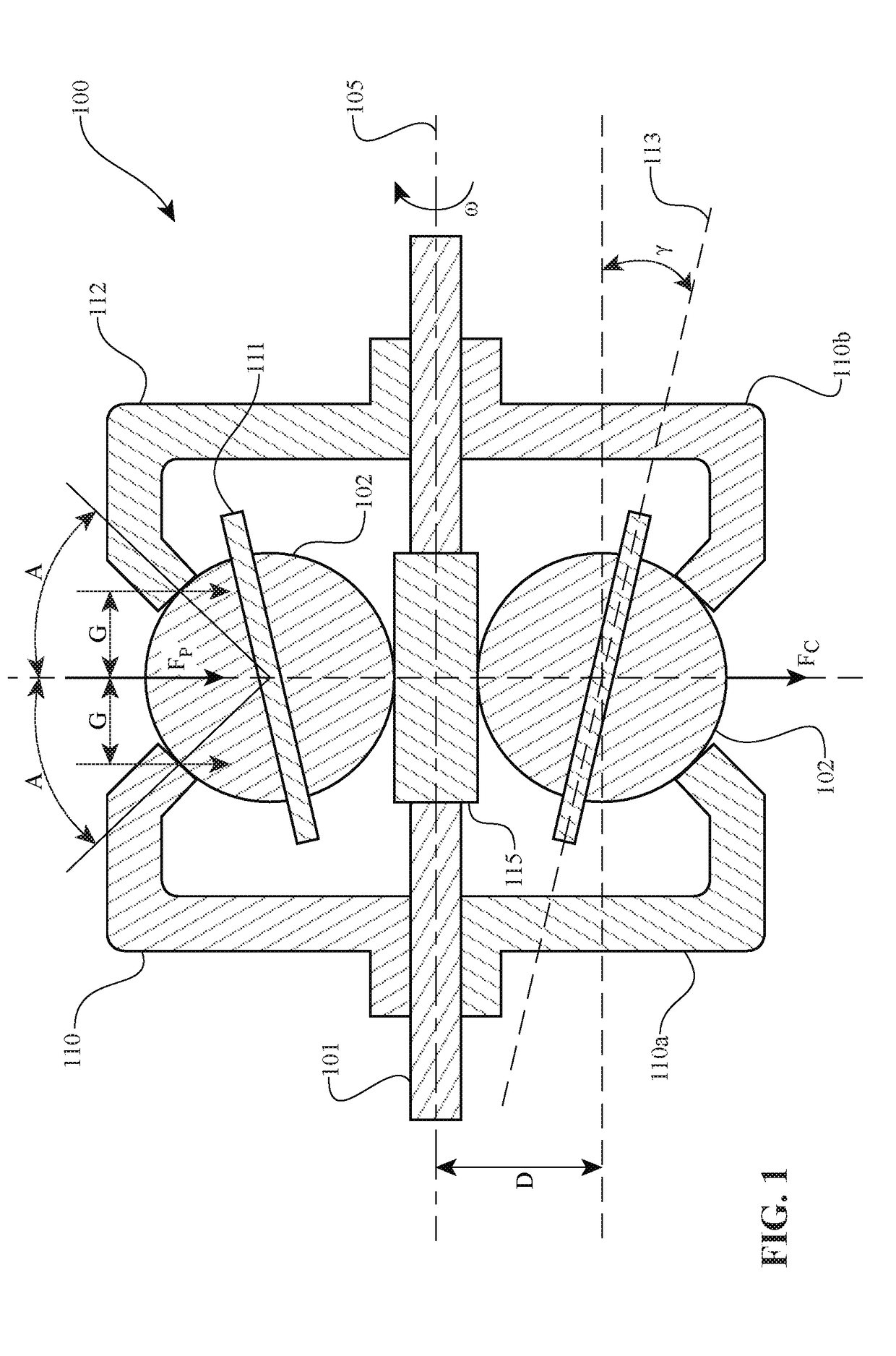
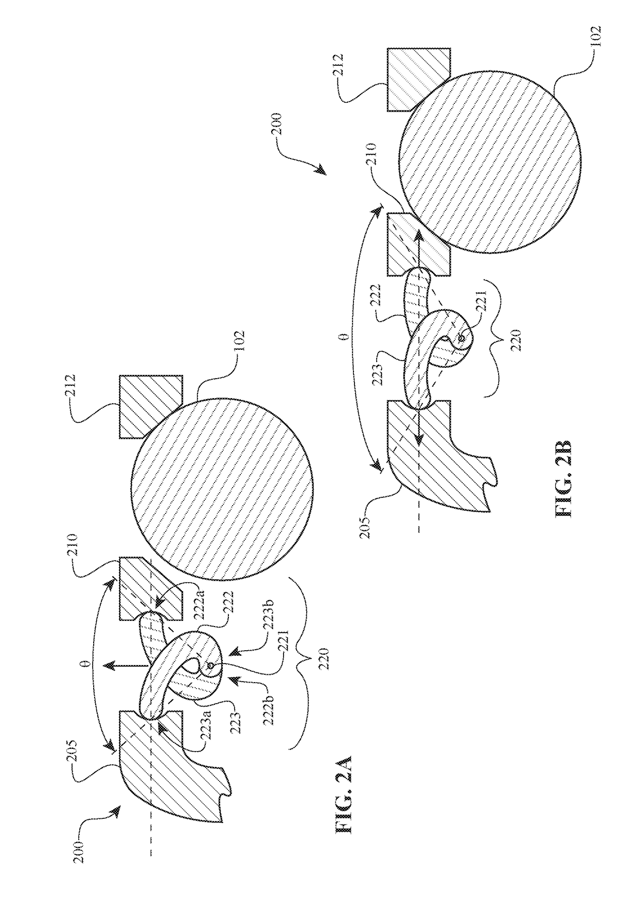
The patent text describes a force generation mechanism that includes a first rigid member and a second rigid member that form an angle when not exposed to a centripetal force. The mechanism exerts an increase in centripetal force at higher rotational velocities, causing the first and second rigid members to form a second angle. The force generationsystem also includes a support structure that exerts a first axial force when the centripetal force is less than a predetermined value and a second axial force when the centripetal force exceeds a predetermined value. The speed based axial force generation mechanism has a linear or non-linear generation rate that increases or decreases as the centripetal force increases or decreases. The technical effects of this mechanism include improved force generation at higher rotational velocities and a more linear or non-linear generation rate that can be adjusted for different centripetal force values.
Problems solved by technology
However, the operating speed, the power source, or the power load may cause slip or otherwise bias the CVT into an unwanted state in which slipping and other negative effects may occur.
Method used
Image
Click on the blue label to locate the original text in one second.
Reading with bidirectional positioning of images and text.
Examples
Embodiment Construction
[0015]The preferred embodiments will now be described with reference to the accompanying figures, wherein like numerals refer to like elements throughout. The terminology used in the description presented herein is not intended to be interpreted in any limited or restrictive manner simply because it is being utilized in conjunction with a detailed description of certain specific embodiments of the invention. Furthermore, embodiments of the invention may include several novel features, no single one of which is solely responsible for its desirable attributes or which is essential to practicing the inventions herein described.
[0016]As used here, the terms “operationally connected,”“operationally coupled”, “operationally linked”, “operably connected”, “operably coupled”, “operably linked,” and like terms, refer to a relationship (mechanical, linkage, coupling, etc.) between elements whereby operation of one element results in a corresponding, following, or simultaneous operation or act...
PUM
Abstract
A speed based axial force generation mechanism may generate axial force corresponding to a rotational speed of a speed based axial force generation system relative to a central axis. As the speed based axial force generationsystem rotates at increasing speeds, inertia causes a change in the configuration of a first rigid member and a second rigid member, resulting in a change in the axial force generated by the mechanism.
Description
BACKGROUNDField of the Disclosure[0001]Embodiments disclosed herein relate generally to continuously variable transmissions (CVTs), including infinitely variable transmissions (IVTs). More particularly, embodiments relate to CVTs and their components, as well as subassemblies and systems which may generate an axial force independent of the features, available power paths, and configurations possible with a CVT.Description of the Related Art[0002]Continuously variable transmissions (CVTs) are being used ever more increasingly in systems in which shift shock, gear collisions, and other mechanical events are known to occur. CVTs such as those described in U.S. Pat. Nos. 7,011,600, 7,238,136, 7,198,585, 7,250,018, 7,166,056, 7,235,031, 7,169,076, 7,288,042, 7,396,209, 8,066,614, 7,731,615, 7,651,437, 7,727,108, 7,686,729, 8,267,829, 7,238,137, 7,036,620, 7,238,138, 7,232,395, 7,125,297, 8,469,853, 8,628,443 and 7,322,901 provide smooth acceleration and deceleration by eliminating the me...
Claims
Application Information
Patent Timeline
Application Date:The date an application was filed.
Publication Date:The date a patent or application was officially published.
First Publication Date:The earliest publication date of a patent with the same application number.
Issue Date:Publication date of the patent grant document.
PCT Entry Date:The Entry date of PCT National Phase.
Estimated Expiry Date:The statutory expiry date of a patent right according to the Patent Law, and it is the longest term of protection that the patent right can achieve without the termination of the patent right due to other reasons(Term extension factor has been taken into account ).
Invalid Date:Actual expiry date is based on effective date or publication date of legal transaction data of invalid patent.

