Carding device for preparing p-aramid fiber yarns and application process of carding device
A para-aramid and yarn technology, applied in the field of carding devices for preparing para-aramid yarn, can solve the problems of poor static electricity removal effect and inability to reduce yarn stiffness, so as to reduce yarn stiffness and facilitate humidification operation, quality-enhancing effects
- Summary
- Abstract
- Description
- Claims
- Application Information
AI Technical Summary
Problems solved by technology
Method used
Image
Examples
Embodiment 1
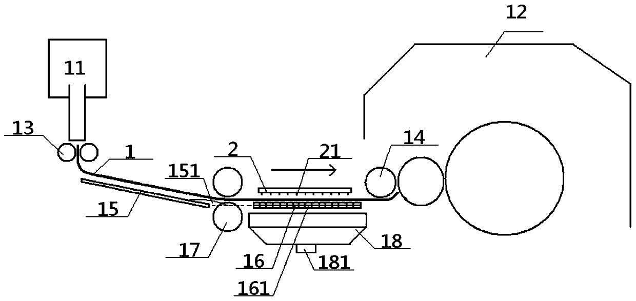
[0059] see figure 1 - Figure 7 , a carding device for preparing para-aramid yarns, comprising a cotton feeding roller 13 and a cotton feeding roller 14, the entrance of the cotton feeding roller 13 communicates with the cotton box 11, and the outlet of the cotton feeding roller 13 communicates with the cotton feeding roller 14 The entrance of the feeding roller 14 is connected with the carding machine 12; the outlet of the feeding roller 13 is connected with the entrance of the inclined pallet 15, and the outlet of the inclined pallet 15 is connected with the entrance of the horizontal pallet 16, and the horizontal The outlet of supporting plate 16 communicates with carding machine 12, and horizontal supporting plate 16 is provided with horizontal pressing plate 2 parallel to it directly above horizontal supporting plate 16, and a plurality of airflow nozzles 21 are arranged in this horizontal pressing plate 2, and the discharge port of this airflow nozzle 21 22 is located b...
Embodiment 2
[0062] Basic content is the same as embodiment 1, the difference is:
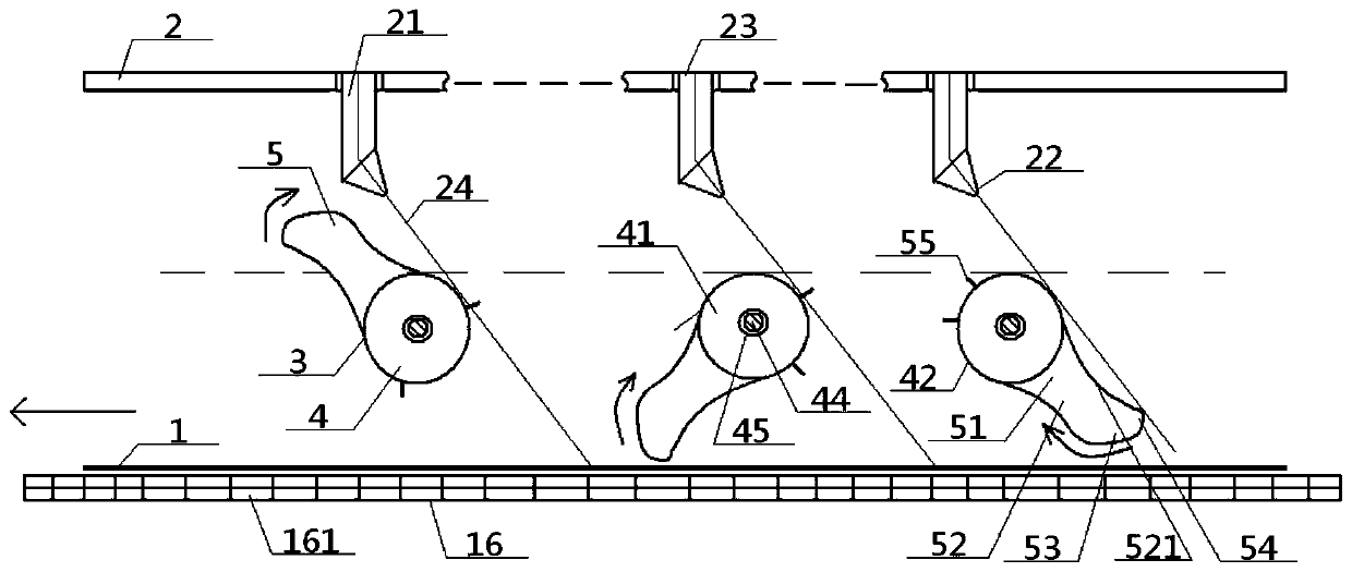
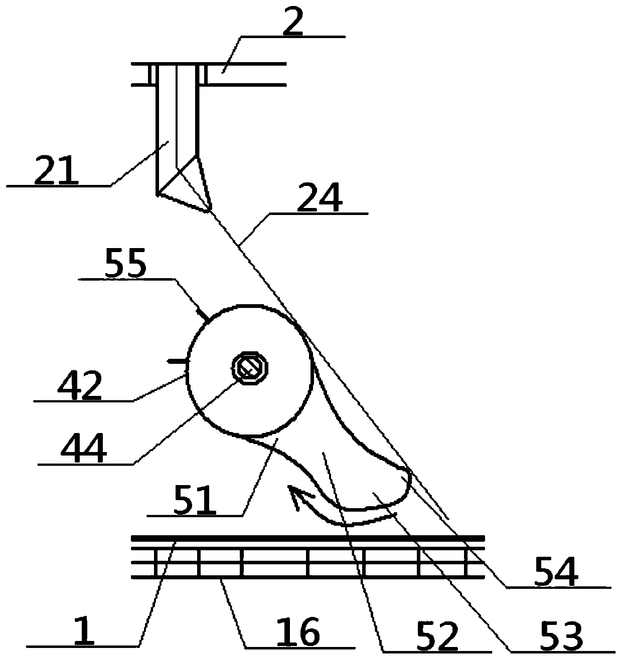
[0063] Structurally: the carding device for preparing para-aramid yarns also includes a plurality of flow-regulating rotary scoops 3 arranged in sequence, the flow-regulating rotary scoops 3 and the airflow nozzles 21 are set up and down one by one, and the flow-regulating rotary scoops 3 are located at the airflow nozzles 21, horizontal Between the supporting plates 16; the flow-adjusting rotating spoon 3 includes a fixed-rotating cylinder 4 and a rotating concave spoon 5, and the fixed-rotating cylinder 4 includes a column side wall 42 and a column top surface 41 and a column bottom surface 43 connected to its two ends, The middle part of the column top surface 41 and the column bottom surface 43 runs through the same column shaft 44. The rotating concave spoon 5 includes a connecting column part 51, a middle waist part 52 and an external pressure part 53. The inner end of the connecting column part 51 Co...
Embodiment 3
[0066] Basic content is the same as embodiment 2, the difference is:
[0067] The air injection path 24 of the discharge port 22 on the air flow nozzle 21 is tangent to the apex of the outer protruding foot 54 in the flow regulating rotary spoon 3 corresponding to the air flow nozzle 21, and the tangent point of the air injection path 24 and the column side wall 42 is located at Between the jet path 24 , the tangent point of the outer lug 54 and the air nozzle 21 .
PUM
| Property | Measurement | Unit |
|---|---|---|
| glass transition temperature | aaaaa | aaaaa |
Abstract
Description
Claims
Application Information
 - R&D
- Intellectual Property
- Life Sciences
- Materials
- Tech Scout
- Unparalleled Data Quality
- Higher Quality Content
- 60% Fewer Hallucinations
Browse by: Latest US Patents, China's latest patents, Technical Efficacy Thesaurus, Application Domain, Technology Topic, Popular Technical Reports.
© 2025 PatSnap. All rights reserved.Legal|Privacy policy|Modern Slavery Act Transparency Statement|Sitemap|About US| Contact US: help@patsnap.com


