Drive structure of nipper of comber

A driving structure and combing machine technology, which is applied in the direction of combing machines, textiles and papermaking, fiber processing, etc., can solve the problem of unsatisfactory nipper transmission mechanism and mode, affecting the service life of the action precision device, and the inertia of mechanical action Large and other problems, to achieve the effect of simple structure, increased driving power, avoiding running inertia and vibration

Inactive Publication Date: 2011-05-11
SHANGHAI TEXTILE MACHINERY COMPLEX
View PDF6 Cites 0 Cited by
  • Summary
  • Abstract
  • Description
  • Claims
  • Application Information

AI Technical Summary

Problems solved by technology

[0006] Although the configuration structure of the prior art can satisfy the basic operation of the nipper, with the continuous progress of the textile industry and the improvement of the requirements for the combing of cotton and chemical fiber materials, the improvement of product quality is realized by the crank-link mechanism. The transmission action of the nipper shaft swing is realized by the crank, slider and slide bar mechanism. After the mechanical size is determined, the displacement, speed and acceleration of the nipper movement are also fixed, and cannot be adjusted at will, and cannot adapt to subtle changes. Therefore, the nipper transmission mechanism and method in the prior art are not satisfactory, and the field hopes to provide a transmission device and mechanism that can adjust the nipper operating characteristics more conveniently and freely, and conform to the simulation of more characteristic curves.
[0007] At the same time, the crank-connecting rod transmission method in the prior art has a complex structure, difficult processing, high cost, relatively large structure, large vibration and impact on the equipment, and large operating inertia caused by mechanical action, which affects the accuracy of the action and the device. service life, those skilled in the art also hope to have a breakthrough change

Method used


Image

  • Drive structure of nipper of comber
  • Drive structure of nipper of comber
  • Drive structure of nipper of comber

Examples


Embodiment 1

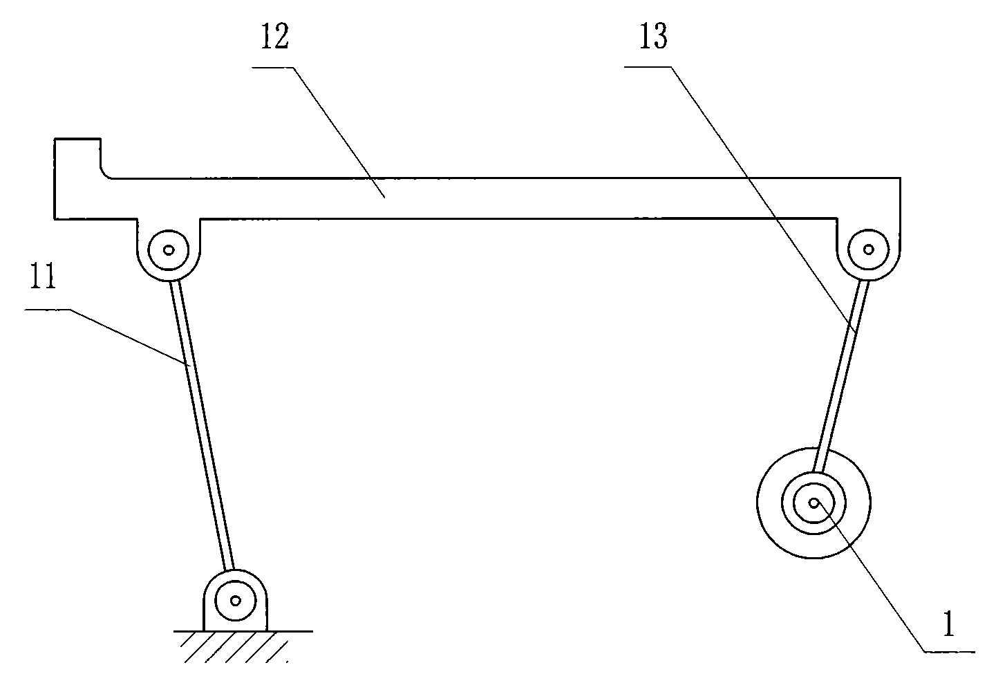
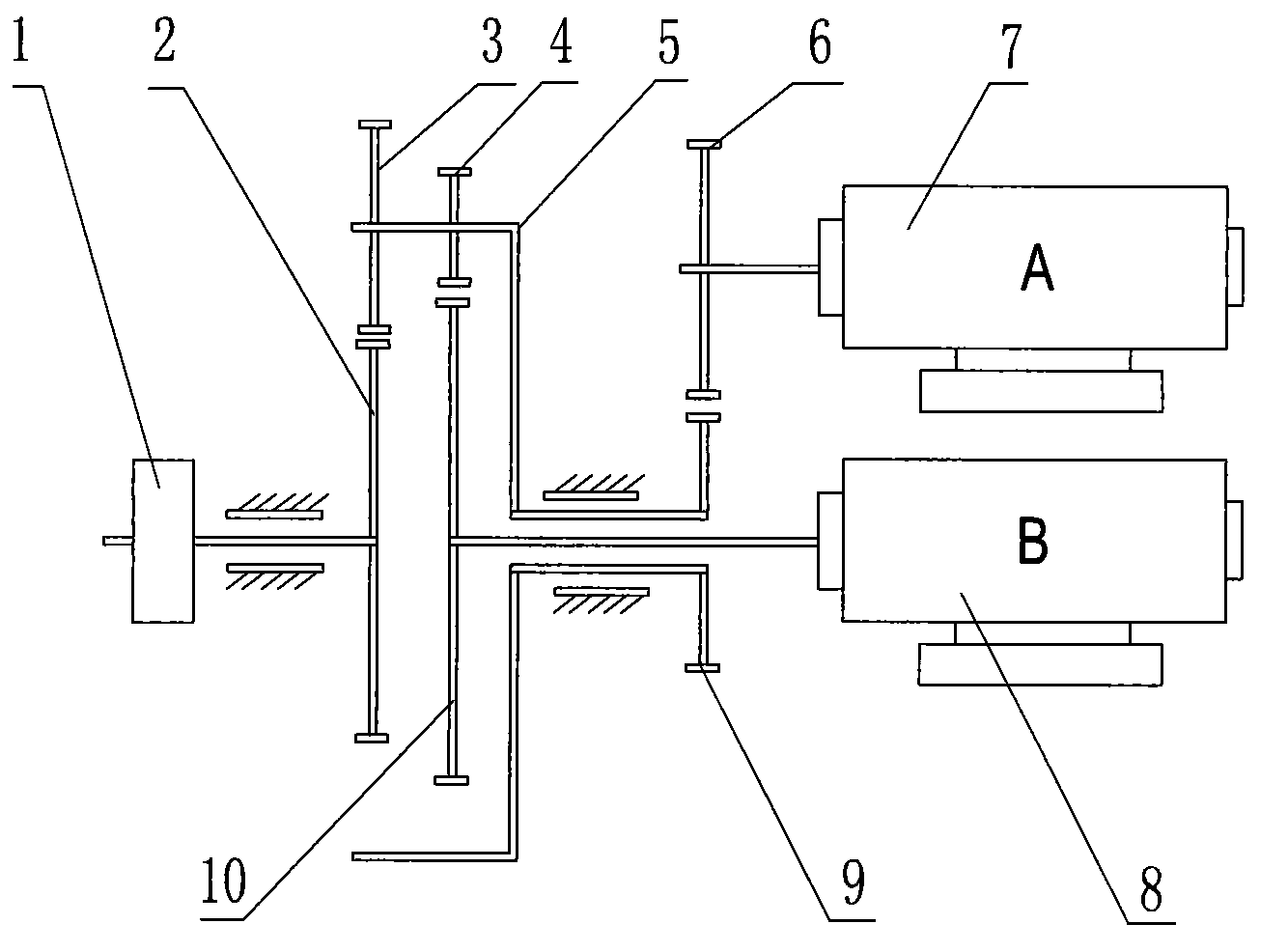
[0027] A driving structure for the nipper of a combing machine. One fulcrum of the nipper 12 is rotatably connected to a support rod 11 which is rotatably connected to a base at the lower part, and another fulcrum of the nipper 12 is rotatably connected to another support rod 13 at the lower part to support The lower end of the rod 13 is fixedly connected to the swing wheel 1 of the servo motor mechanism. The servomotor mechanism is two servomotors, wherein one A servomotor 7 meshes with the planet carrier gear 9 of a planetary gear through the A servomotor gear 6, and the other B servomotor 8 meshes with the sun gear 10 of the planetary gear. The rear planetary gear 4 meshes, and the front planetary wheel 3 meshes with the output gear 2, and the output gear 2 is coaxially connected to the swing wheel 1.

[0028] A servo motor 7 and B servo motor 8 are synthesized on an output gear 2 through a planetary gear mechanism, which not only improves the power to drive the nipper 12, ...

Embodiment 2

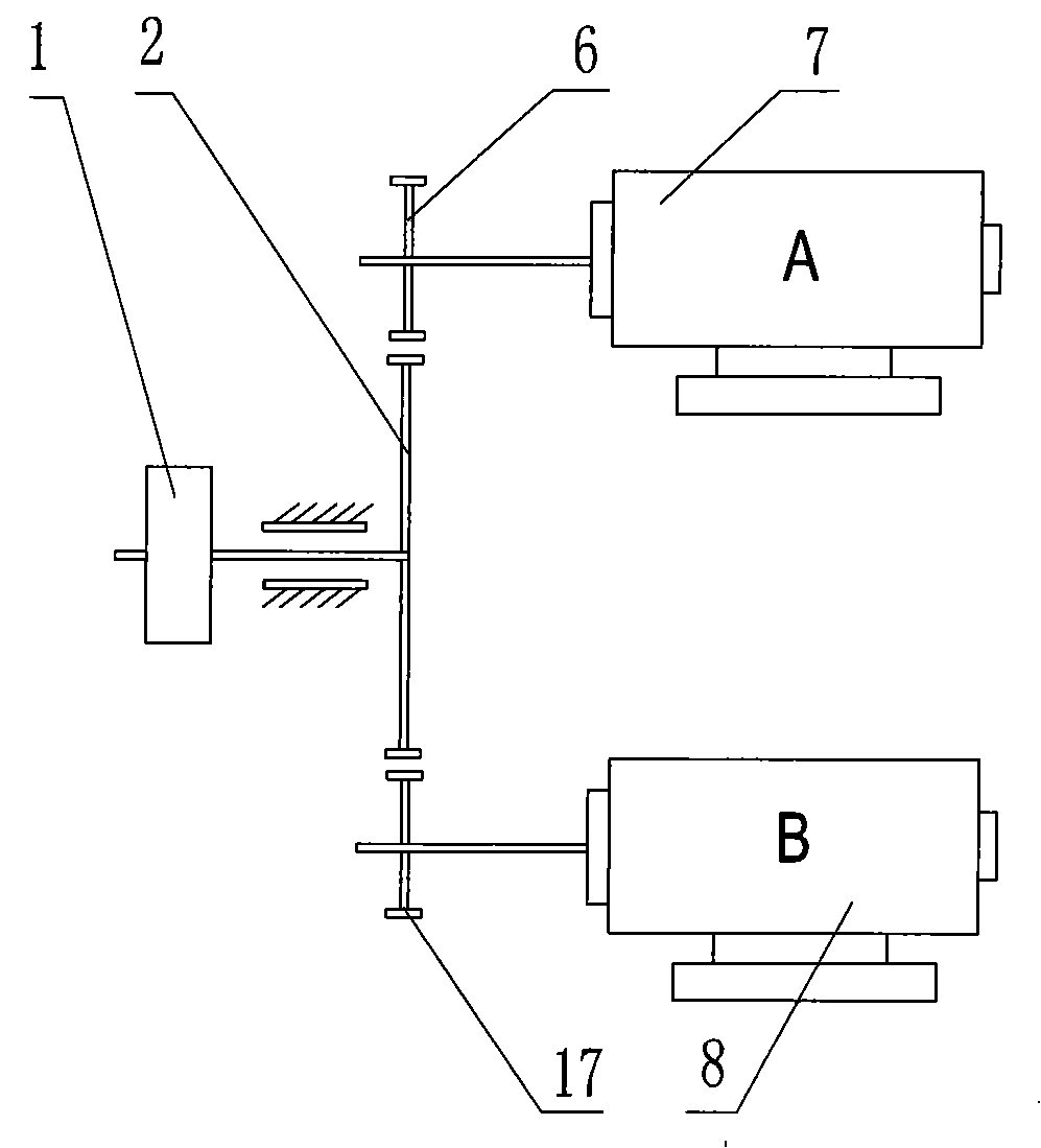
[0030] A driving structure for the nipper of a combing machine. One fulcrum of the nipper 12 is rotatably connected to a support rod 11 which is rotatably connected to a base at the lower part, and another fulcrum of the nipper 12 is rotatably connected to another support rod 13 at the lower part to support The lower end of the rod 13 is fixedly connected to the swing wheel 1 of the servo motor mechanism. The servo motor mechanism is that the A servo motor gear 6 and the B servo motor gear 9 of the two servo motors are both meshed with the coaxial output gear 2 of the swing wheel 1 .

[0031] A servo motor 7 and B servo motor 8 two servo motors directly mesh to drive an output gear 2, and the rotation of the output gear 2 rotates through the eccentric wheel 18 to connect another fulcrum of the nipper 12 to realize the swing operation of the nipper 12. The two servo motors have both improved the power to drive the nipper 12, and are driven by computer programming to drive and c...


PUM


Abstract

The invention relates to a power transmission mode and a structure of a nipper of a comber. In a drive structure of the nipper of the comber, a pivot of the nipper (12) is rotatablely connected with a support bar (11) which is positioned on the lower part and is rotatablely connected with a base. A wobble wheel (1) of a servo motor mechanism is connected with the other pivot of the nipper (12) byan eccentric wheel (18) in an eccentrically rotating manner. A servo motor A (7) of two servo motors is meshed with a planetary carrier gear (9) of a planetary gear by a gear (6) of the servo motor A, and the other servo motor B (8) is meshed with a rear planetary gear (4) by a central gear (10) of the planetary gear. A front planetary gear (3) is meshed with a drive output gear (2) which is coaxially connected with the wobble wheel (1). The gear (6) of the servo motor A and a gear (9) of the servo motor B can be both meshed with a coaxial output gear (2) of the wobble wheel (1). The motion trail of the nipper is adjustable, thus conducing to optimizing the nipper motion, simplifying the structure and conducing to improving the speed of the comber and the combing quality.

Description

(1) Technical field [0001] The invention relates to a nipper part structure of a combing machine in the textile industry, in particular to a power driving structure of a combing machine nipper. (2) Background technology [0002] It is known that in order to improve the quality of chemical fiber cotton and wool fabrics, an important process in textile engineering is combing sliver, and its function is to remove short fibers, impurities, cotton, etc. Knots and defects, etc., and also improve the straightness of cotton fibers, so that the combed cotton sliver can finally be spun into high-count yarns with more than 60 counts and a glossy appearance through the subsequent process, so as to satisfy people's comfortable dressing or some special needs. Therefore, the comber is an indispensable equipment for spinning high-count yarn and blended products. [0003] The main working parts and their functions of the combing machine are as follows: head transmission mechanism - impleme...

Claims


Application Information

Patent Timeline
Patent Type & Authority Patents(China)
IPC IPC(8): D01G19/26D01G19/16
Inventor 张慧芳王宝昌尤长根李华
Owner SHANGHAI TEXTILE MACHINERY COMPLEX
Why Eureka
Try Eureka