Real-time visual-inertial motion tracking fault detection

a technology of motion tracking and real-time visual, applied in the field of motion tracking, can solve problems such as reducing the quality of user experien

Active Publication Date: 2017-11-23
GOOGLE LLC
View PDF4 Cites 11 Cited by
  • Summary
  • Abstract
  • Description
  • Claims
  • Application Information

AI Technical Summary

Problems solved by technology

If a device is unable to identify its pose, the quality of the user experience is reduced.

Method used


Image

  • Real-time visual-inertial motion tracking fault detection
  • Real-time visual-inertial motion tracking fault detection
  • Real-time visual-inertial motion tracking fault detection

Examples


Embodiment Construction

[0016]It should be understood at the outset that although an illustrative implementation of one or more embodiments are provided below, the description is not to be considered as limiting the scope of the embodiments described herein. The disclosure may be implemented using any number of technique, whether currently known or in existence. The disclosure should in no way be limited to the illustrative implementations, drawings, and techniques illustrated and described herein, which may be modified within the scope of the appended claims along with a full scope of equivalence.

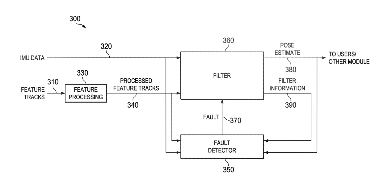
[0017]The present disclosure provides a fault detection system to detect fault conditions when a visual-inertial odometry (VIO) estimator of an electronic device is unable to accurately estimate the motion of the device. The fault detection system includes a plurality of subdetectors that independently operate to detect different failure conditions in a motion tracking system. If any of these subdetectors detect ...


PUM


Abstract

Fault detection for real-time visual-inertial odometry motion tracking. A fault detection system allows immediate detection of error when the motion of a device cannot be accurately determined. The system includes subdetectors that operate independently and in parallel to a main system on a device to determine if a condition exists which results in a main system error. Each subdetector covers a phase of a six-degrees of freedom (6DOF) estimation. If any of the subdetectors detect an error, a fault is output to the main system to indicate a motion tracking failure.

Description

CROSS-REFERENCE TO RELATED APPLICATIONS[0001]The present application claims priority to U.S. Patent Application Ser. No. 62 / 337,987 (Attorney Docket No. 1500-G16013-PR), entitled “Methods And Systems For VR / AR Functionality In A Portable Device” and filed on 18 May 2016, the entirety of which is incorporated by reference herein for all purposes.BACKGROUNDField of the Disclosure[0002]The present disclosure relates generally to motion tracking and a system for detecting and recovering from faults during motion tracking.Description of the Related Art[0003]Motion tracking allows a device to understand its motion with respect to position and orientation as it moves through an area. Motion tracking is useful in virtual reality applications such as gaming which allows a user to explore a virtual world from a fixed viewpoint. The tracked motion can be characterized by how many degrees of freedom are possible in movement, for example, either three degrees of freedom (3DoF) or six degrees of ...

Claims


Application Information

Patent Timeline
Patent Type & Authority Applications(United States)
IPC IPC(8): G01P21/00G01C19/00G06F3/01G06F17/18G06T7/73
CPCG01P21/00G01C19/00G06F17/18G06F3/011G06T7/74G06F3/038G01S5/0294
Inventor LI, MINGYANGHESCH, JOELMORATTO, ZACHARY
Owner GOOGLE LLC
Why Eureka
Try Eureka