Gyroscopic attitude control system

Active Publication Date: 2017-11-23
RAYTHEON CO
View PDF29 Cites 16 Cited by
  • Summary
  • Abstract
  • Description
  • Claims
  • Application Information

AI Technical Summary

Benefits of technology

[0024]According to an embodiment of any paragraph(s) of this summary, the attitude control system is part of a flight vehicle.
[0025]According to another aspect of the invention, an attitude control system includes: three control moment gyro pairs for controlling attitude in respective control moment axes, wherein each of the control moment gyro pairs includes: a first control moment gyro that includes a first flywheel rotatably mounted to a first frame, wherein the first flywheel rotates relative to the first frame about a first flywheel rotation axis; a second control moment gyro that includes a second flywheel rotatably mounted to a second frame, wherein the second flywheel rotates

Problems solved by technology

Control of flight vehicles, such as hypersonic vehicles, can be a challenging problem, due a number of non-linear phenomena.
Control surfaces are not useful for space vehicles, or where the atmosphere is too thin for them to result in sufficient drag forces.
Reaction wheels are inefficiency, although simple to use.
Prior control moment gyros (CMGs) have greater torque efficiency, but suffer from numerous disadvantages, such as axial crosstalk, operational complexity, and singularities.

Method used


Image

  • Gyroscopic attitude control system
  • Gyroscopic attitude control system
  • Gyroscopic attitude control system

Examples


Embodiment Construction

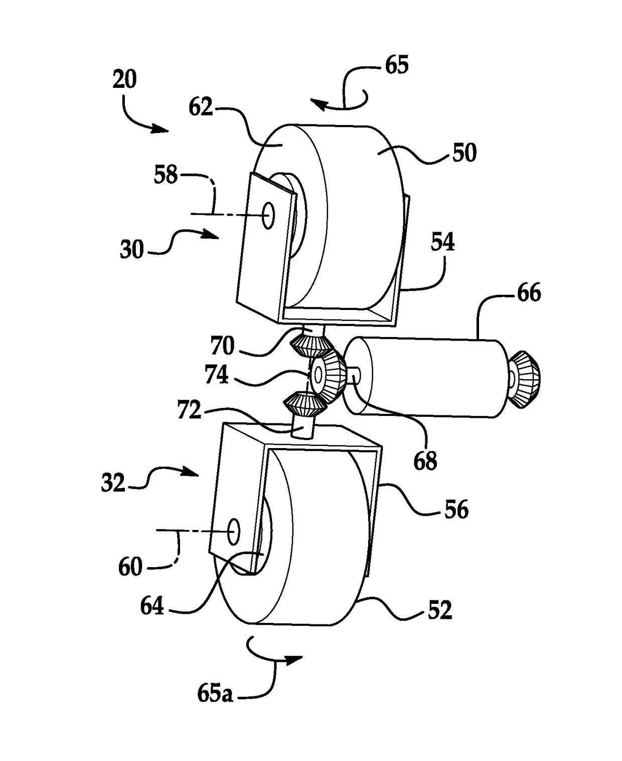
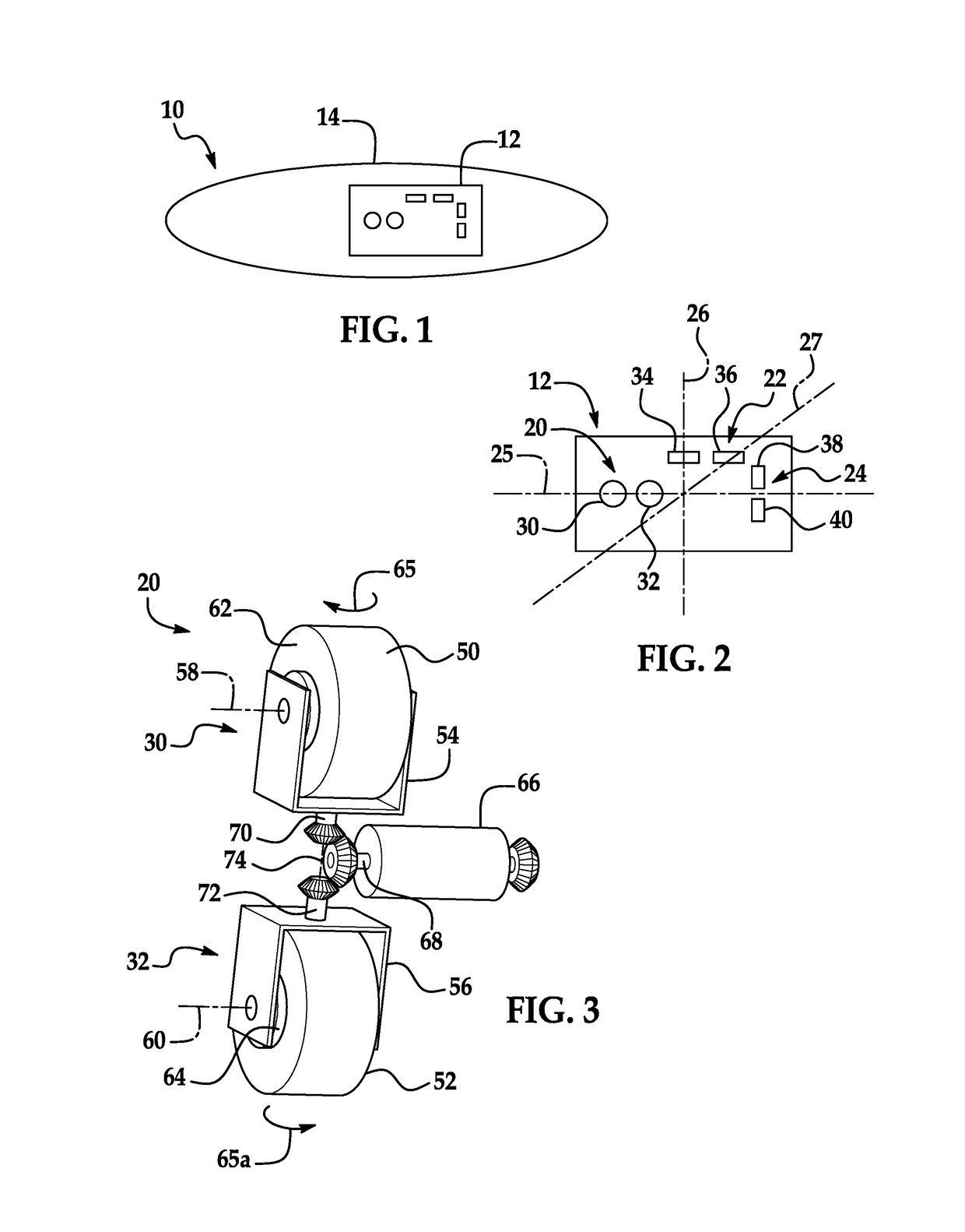
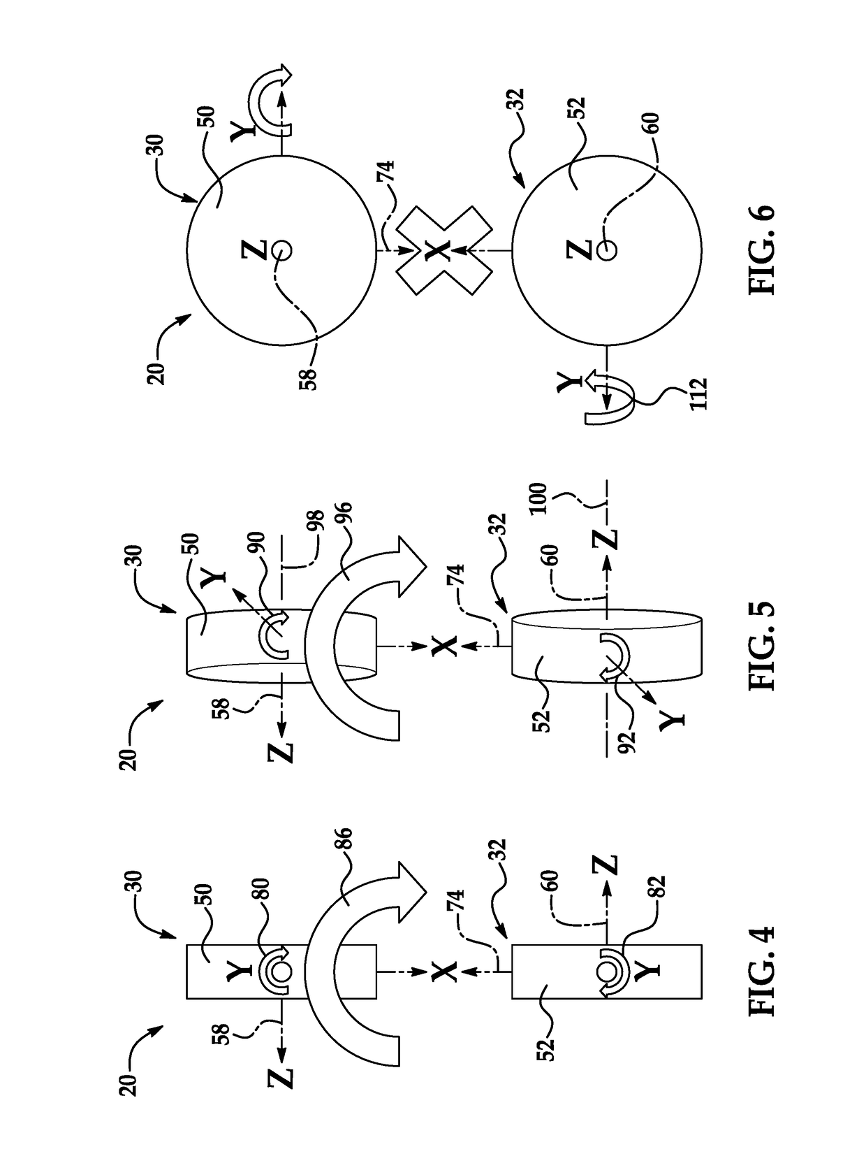
[0040]An attitude control system includes one or more control moment gyro pairs, with gyros of individual of the pairs being counter-rotated to rotate the rotation axes of flywheels of the gyros of a gyro pair in opposite direction. The flywheels of a gyro pair may be in paddle configuration, with the rotation axes of the flywheels rotating in the counter-rotation through separate planes as the gyros are rotated. The rotation of the gyros of a gyro pair may be accomplished by coupling both of the gyros to a servo motor with suitable coupling gears, or by using independent servos for each gyro. The counter-rotation of gyros of an individual pair produces a resultant torque about a fixed global axis, such as the axis of a flight vehicle of which the attitude control system is a part. Further control may be accomplished by varying the rotation speeds of the flywheels, such as by use of variable speed motors and by use of variable speed servo motors to counter-rotate the gyro pairs inde...


PUM


Abstract

An attitude control system includes one or more control moment gyro pairs, with gyros of individual of the pairs being counter-rotated to rotate the rotation axes of flywheels of the gyros of a gyro pair in opposite direction. The flywheels of a gyro pair may be in paddle configuration, with the rotation axes of the flywheels rotating in the counter-rotation through separate planes as the gyros are rotated. The rotation of the gyros of a gyro pair may be accomplished by coupling both of the gyros to a servo motor with suitable coupling gears, or by using independent servos for each gyro. The counter-rotation of gyros of an individual pair produces a resultant torque about a fixed global axis, such as the axis of a flight vehicle of which the attitude control system is a part. Further control may be accomplished for example by varying rotation speeds of the flywheels.

Description

FIELD OF THE INVENTION[0001]The invention is in the field of attitude control systems, such as attitude control systems used for flight vehicles.DESCRIPTION OF THE RELATED ART[0002]Control of flight vehicles, such as hypersonic vehicles, can be a challenging problem, due a number of non-linear phenomena. Control surfaces are not useful for space vehicles, or where the atmosphere is too thin for them to result in sufficient drag forces. Reaction wheels are inefficiency, although simple to use. Prior control moment gyros (CMGs) have greater torque efficiency, but suffer from numerous disadvantages, such as axial crosstalk, operational complexity, and singularities.[0003]In view of this history there is room for an improved attitude control system, usable for flight vehicles such as space vehicles or hypersonic vehicles.SUMMARY OF THE INVENTION[0004]An attitude control system includes a pair of aligned flywheels that are counter-rotated relative to one another, to produce a resultant t...

Claims


Application Information

Patent Timeline
IPC IPC(8): G05D1/08G01C19/04B64G1/28B64G1/24F42B10/02
CPCG05D1/0808B64G1/286F42B10/025G01C19/04B64G2001/245G05D1/0883B64C19/00B64G1/244B64G1/245
Inventor ALA, EERO H.OWAN, CHRISTOPHER P.
Owner RAYTHEON CO
Why Eureka
Try Eureka