Image formation apparatus

a technology of image formation apparatus and image, which is applied in the direction of electrographic process apparatus, instruments, optics, etc., can solve the problems of deterioration in the productivity of printed matters, and achieve the effect of improving the productivity of printing and decreasing the frequency of detection

Inactive Publication Date: 2017-11-30
OKI DATA CORP
View PDF2 Cites 3 Cited by
  • Summary
  • Abstract
  • Description
  • Claims
  • Application Information

AI Technical Summary

Benefits of technology

[0006]An object of an embodiment of the invention is to improve productivity of printed matters by decreasing frequency of detection of amounts of image misregistration and frequency of image misregistration correction.
[0008]According to the aspect of the invention, it is possible to improve productivity of printing by decreasing frequency of detection of amounts of image misregistration and frequency of image misregistration correction.

Problems solved by technology

As a consequence, execution of detection of amounts of image misregistration (amounts of color misregistration) and correction of image misregistration with high frequency causes a problem of deterioration in productivity of printed matters.

Method used


Image

  • Image formation apparatus
  • Image formation apparatus
  • Image formation apparatus

Examples


first embodiment

> First Embodiment

[0022]> Configuration

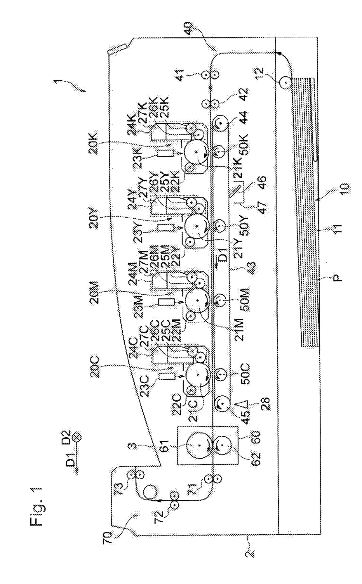
[0023]FIG. 1 is a cross-sectional view illustrating a schematic structure of image formation apparatus 1 according to one or more embodiments. Image formation apparatus 1 is a color printer which adopts electrophotography, for example.

[0024]As illustrated in FIG. 1, image formation apparatus 1 includes: multiple image formation units 20K, 20Y, 20M, and 20C which form developer images (toner images) on record medium P such as a sheet of paper; and medium supply unit (separation roller unit) 10 which supplies record medium P to multiple image formation units 20K, 20Y, 20M, and 20C. Moreover, image formation apparatus 1 includes: conveyance unit 40 which conveys record medium P supplied from medium supply unit 10; transfer rollers (transfer units) 50K, 50Y, 50M, and 50C disposed in such a way as to correspond to the multiple image formation units 20K, 20Y, 20M, and 20C, respectively; and a fuser 60 which causes the developer images (the toner imag...

second embodiment

> Second Embodiment

[0068]FIG. 10 is a cross-sectional view illustrating a schematic configuration of image formation apparatus 100 according to one or more embodiments. FIG. 11 is a perspective view illustrating the schematic configuration of image formation apparatus 100. FIG. 12 is another cross-sectional view illustrating the schematic configuration of image formation apparatus 100. In FIGS. 10, 11, and 12, constituents which are identical or corresponding to the constituents illustrated in FIG. 1 are denoted by the same reference numerals as those indicated in FIG. 1.

[0069]Image formation apparatus 100 is different from image formation apparatus 1 in that image formation apparatus 100 includes first cover 171 serving as an opening-closing member to open and close an opening of housing 2. As illustrated in FIGS. 11 and 12, image formation apparatus 100 includes the opening, housing 2 to house the multiple image formation units attached to the apparatus body, and first cover 171 s...


PUM


Abstract

An image formation apparatus that includes: first to third image formation units provided in this order in a traveling direction of a transfer target medium; a detector configured to detect first to third correction pattern formed on the transfer target medium by the first to third image formation units, respectively; and a control unit programed to control image misregistration correction based on a result of detection by the detector. The control unit causes the first and third image formation units to form the first and third correction patterns on the transfer target medium, respectively. When an amount of image misregistration between the first correction pattern and the third correction pattern is less than a predetermined value, the control unit neither causes the second image formation unit to form the second correction pattern, nor executes the image misregistration correction.

Description

CROSS REFERENCE TO RELATED APPLICATIONS[0001]This application claims priority based on 35 USC 119 from prior Japanese Patent Application No. 2016-104971 filed on May 26, 2016, entitled “IMAGE FORMATION APPARATUS”, the entire contents of which are incorporated herein by reference.BACKGROUND OF THE INVENTION1. Field of the Invention[0002]This disclosure is related to an image formation apparatus including multiple image formation units.2. Description of Related Art[0003]A color image formation apparatus which prints a color image generally includes multiple image formation units that are arranged in a conveyance direction (a traveling direction) of record media. Developer images of multiple colors formed by using the multiple image formation units are sequentially transferred onto a record medium to be conveyed. As a result, a color developer image, which is formed from the developer images of multiple colors overlapping one another, is formed on the record medium. The color developer...

Claims


Application Information

Patent Timeline
Patent Type & Authority Applications(United States)
IPC IPC(8): G03G15/00G03G15/16G03G15/01
CPCG03G15/6558G03G15/16G03G15/01G03G15/5058G03G2215/0141G03G2215/0158G03G2215/0161
Inventor SHIRAISHI, TOYOKAZU
Owner OKI DATA CORP
Why Eureka
Try Eureka