
Electric power conversion circuit including switches and bootstrap circuits, and electric power transmission system including electric power conversion circuit

a technology of electric power conversion circuit and electric power transmission system, which is applied in power conversion systems, ac-dc conversion, electrical equipment, etc., can solve the problems of inferior power generation capability of most renewable energy sources connected to such local small-scale electric power networks

Active Publication Date: 2017-11-30
PANASONIC INTELLECTUAL PROPERTY MANAGEMENT CO LTD
View PDF5 Cites 2 Cited by
  • Summary
  • Abstract
  • Description
  • Claims
  • Application Information

AI Technical Summary

Benefits of technology

The patent text discusses the issues with small-scale electric power networks connected to renewable energy sources. These networks often have weaker power generation capabilities and more fluctuations in power output compared to large commercial networks. To address this, the patent proposes a technique for interchanging electric power through a transmission route that improves efficiency and allows for stable and efficient operation of the small-scale network.

Problems solved by technology

Most renewable energy sources connected to such local small-scale electric power networks are inferior in power generation capability to and is larger in fluctuation of power generation capability than main power sources of the conventional large-scale commercial electric power networks.

Method used


Image

  • Electric power conversion circuit including switches and bootstrap circuits, and electric power transmission system including electric power conversion circuit
  • Electric power conversion circuit including switches and bootstrap circuits, and electric power transmission system including electric power conversion circuit
  • Electric power conversion circuit including switches and bootstrap circuits, and electric power transmission system including electric power conversion circuit

Examples


first embodiment

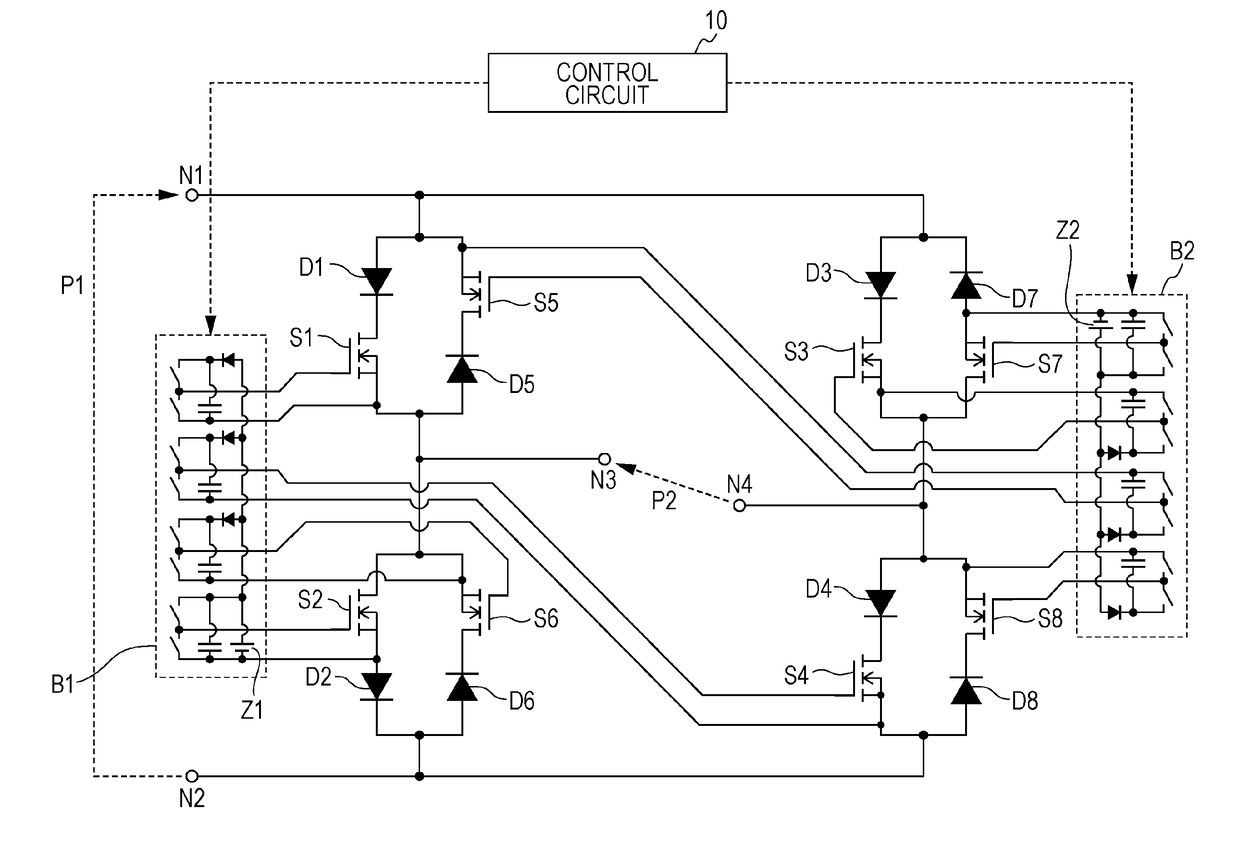
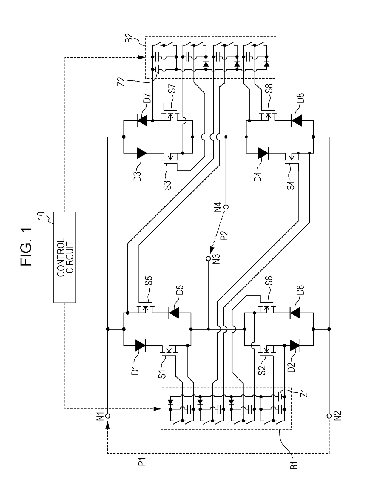
[0041]FIG. 1 is a circuit diagram illustrating a configuration of an electric power conversion circuit according to a first embodiment. The electric power conversion circuit illustrated in FIG. 1 includes port terminals N1 through N4, diodes D1 through D8, switches S1 through S8, bootstrap circuits B1 and B2, and a control circuit 10.

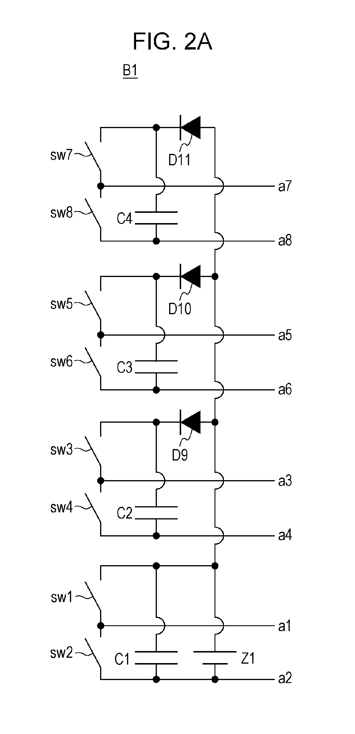
[0042]The port terminals N1 through N4 are examples of “first through fourth port terminals” of the present disclosure, respectively. The diodes D1 through D8 are examples of “first through eighth diodes” of the present disclosure, respectively. The switches S1 through S8 are examples of “first through eighth switches” of the present disclosure, respectively. The bootstrap circuits B1 and B2 are examples of “first and second bootstrap circuits” of the present disclosure, respectively.

[0043]The electric power conversion circuit illustrated in FIG. 1 converts and transmits direct-current electric power or alternating-current electric power bi-directionall...

second embodiment

[0093]FIG. 14 is a block diagram illustrating an outline configuration of an electric power transmission system according to a second embodiment. The electric power transmission system illustrated in FIG. 14 includes at least one generator 1, which is a power source, at least one electric power load 2, which is a load, an electric power line 3, and electric power conversion circuits M1 and M2 according to the first embodiment. The electric power line 3 includes, for example, a wire for transmitting electric power. The electric power conversion circuit M1 is provided between a designated one of the at least one generator 1 and the electric power line 3 and is used as at least one electric power transmitting device. The electric power conversion circuit M2 is provided between the electric power line 3 and a designated one of the at least one load and is used as at least one electric power receiving device.

[0094]An identical code sequence is given to the electric power conversion circu...


PUM


Abstract

An electric power conversion circuit includes: first through fourth port terminals; first through fourth switches that are connected with each other in a bridge configuration; fifth through eighth switches that are respectively connected in parallel with the first through fourth switches; first through eighth diodes that are respectively connected in series with the first through eighth switches; a first bootstrap circuit that is connected to control terminals of the first, second, fourth, and sixth switches; and a second bootstrap circuit that is connected to control terminals of the third, fifth, seventh, and eighth switches.

Description

BACKGROUND1. Technical Field[0001]The present disclosure relates to an electric power conversion circuit and an electric power transmission system in which electric power is transmitted from a power source to a load through an electric power line by using the electric power conversion circuit as an electric power transmitting device or an electric power receiving device.2. Description of the Related Art[0002]In recent years, renewable energy represented by solar power, wind power, biofuel power, and the like is increasingly introduced in addition to conventional electric power such as thermal power, hydropower, and nuclear power provided by electric power companies. Furthermore, in addition to existing large-scale commercial electric power networks, introduction of local small-scale electric power networks that enable local production for local consumption of electric power is spreading throughout the world for the purpose of reducing loss during long-distance electric power transmi...

Claims


Application Information

Patent Timeline
Patent Type & Authority Applications(United States)
IPC IPC(8): H02M7/53862H02M7/5387H02M7/5395
CPCH02M7/53862H02M7/5395H02M7/5387H02M1/08H02M1/32H02M7/797H02M1/0006
Inventor NISHIMOTO, TAIKIYAMAMOTO, ATSUSHIHARA, SHOICHI
Owner PANASONIC INTELLECTUAL PROPERTY MANAGEMENT CO LTD
Learn More