
Discrete dynode electron multiplier fabrication method

a fabrication method and electron multiplier technology, applied in the direction of electron multiplier details, multiplier electrode arrangement, photo-emissive cathode manufacturing, etc., can solve the problems of inventory and cost perspective, disadvantages from assembly and inventory perspectives

Active Publication Date: 2017-12-07
ADAPTAS SOLUTIONS LLC
View PDF5 Cites 8 Cited by
  • Summary
  • Abstract
  • Description
  • Claims
  • Application Information

AI Technical Summary

Benefits of technology

The patent describes an invention related to a discrete-dynode electron multiplier (DDEM) and a method for fabricating it. The invention involves mounting an insulator block to a monolithic conductor block and creating a series of ion-optics geometrical structures in the conductor block, which serve to guide electrons to collide with a designated area of a dynode to generate electron multiplication. The structures can be designed for various functions such as an input section, an electron collector, or an electron cloud splitter. The invention also includes the use of an opening in the monolithic conductor block to connect a circuit board, and the availability of different geometrical forms for the conductor and ceramics blocks. The technical effects of the invention include improved efficiency and accuracy of electron multiplication in the DDEM, as well as improved performance and reliability of the overall device.

Problems solved by technology

Conventional DDEMs, such as those disclosed in U.S. Pat. Nos. 7,723,680 and 3,619,692, which are each incorporated by reference herein in their entirety, ordinarily comprise a large number of separate and discrete parts, which is disadvantageous from assembly, inventory and cost perspectives.

Method used


Image

  • Discrete dynode electron multiplier fabrication method
  • Discrete dynode electron multiplier fabrication method
  • Discrete dynode electron multiplier fabrication method

Examples


Embodiment Construction

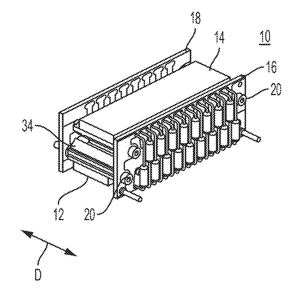
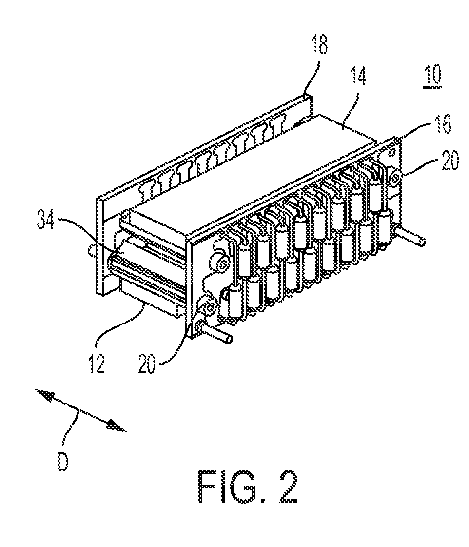
[0020]FIGS. 2 and 3 depict assembled and exploded views, respectively, of a discrete-dynode electron multiplier (DDEM) 10, according to one exemplary embodiment of the invention. DDEM 10 generally comprises a first anode array 12 spaced apart from a second anode array 14, and two circuit boards 16 and 18 that are fixedly mounted on opposing sides of the first anode array 12 and the second anode array 14 by four fasteners 20 and corresponding nuts 22 and washers 24.

[0021]FIG. 4A depicts a side elevation view of the dynode arrays 12 and 14 of the DDEM 10. Arrays 12 and 14 together form an input 34 at one end of DDEM 10 through which ions (electrons) are distributed into DDEM 10, and an output (anode) 36 at an opposite end of DDEM 10 at which the ions (electrons) are collected.

[0022]Each dynode array 12 and 14 includes an insulator 26 and a conductor 30 that is mounted to the insulator 26. Either one or both conductors 30 may be formed from a single, unitary, monolithic block of conduc...


PUM


Abstract

A process of fabricating a discrete-dynode electron multiplier (DDEM) including the steps of mounting an insulator block to a conductor block, and forming a series of ion-optics geometrical structures in the conductor block, each ion-optics geometrical structure having a smallest dimension of less than 1 millimeter. The forming step may be performed by electrical discharge machining (EDM), laser cutting, and / or water jet cutting.

Description

BACKGROUND OF THE INVENTION(1) Field of the Invention[0001]This invention relates to fabrication methods for discrete dynode electron multipliers.(2) Description of Related Art[0002]There are two basic forms of electron multipliers that are commonly used in mass spectrometry, namely, a discrete-dynode electron multiplier (DDEM) and a continuous-dynode electron multiplier. This invention relates to DDEM's and methods for fabricating a DDEM.[0003]As is disclosed in U.S. Pat. No. 7,723,680 to Hidalgo, which is incorporated by reference herein in its entirety, in a conventional DDEM, ions enter the electron multiplier and strike a dynode. In response, the dynode releases a plurality of electrons in response to each ion that strikes it. Those ions then pass to and strike another dynode. The second dynode then releases multiple electrons in response to each electron that strikes it. This process repeats for several stages of dynodes. The electrons are collected by a Faraday cup or plate a...

Claims


Application Information

Patent Timeline
IPC IPC(8): H01J9/12H01J43/26
CPCH01J43/26H01J9/125
Inventor HOSEA, JOSEPHHADJAR, OMAR
Owner ADAPTAS SOLUTIONS LLC
Learn More