
Flexible Variable Speed Genset System

a variable speed, genset technology, applied in the direction of process control, machine control, instruments, etc., can solve the problems of inconvenient operation of the genset at constant speed, uneven and premature wear of the genset system, etc., to achieve better transient performance

Inactive Publication Date: 2017-12-07
CATERPILLAR INC
View PDF7 Cites 2 Cited by
  • Summary
  • Abstract
  • Description
  • Claims
  • Application Information

AI Technical Summary

Benefits of technology

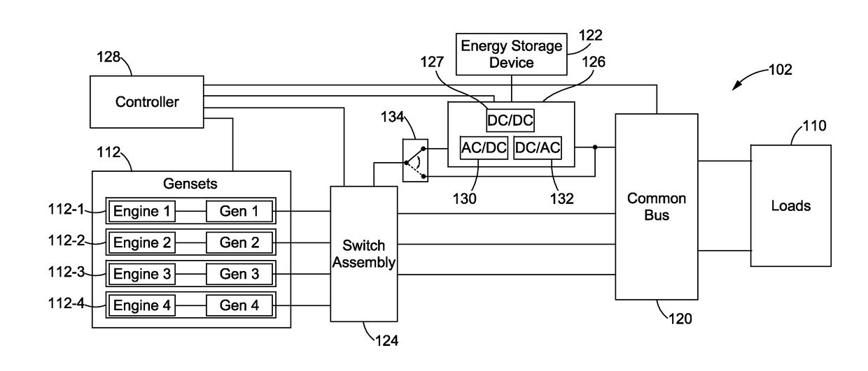
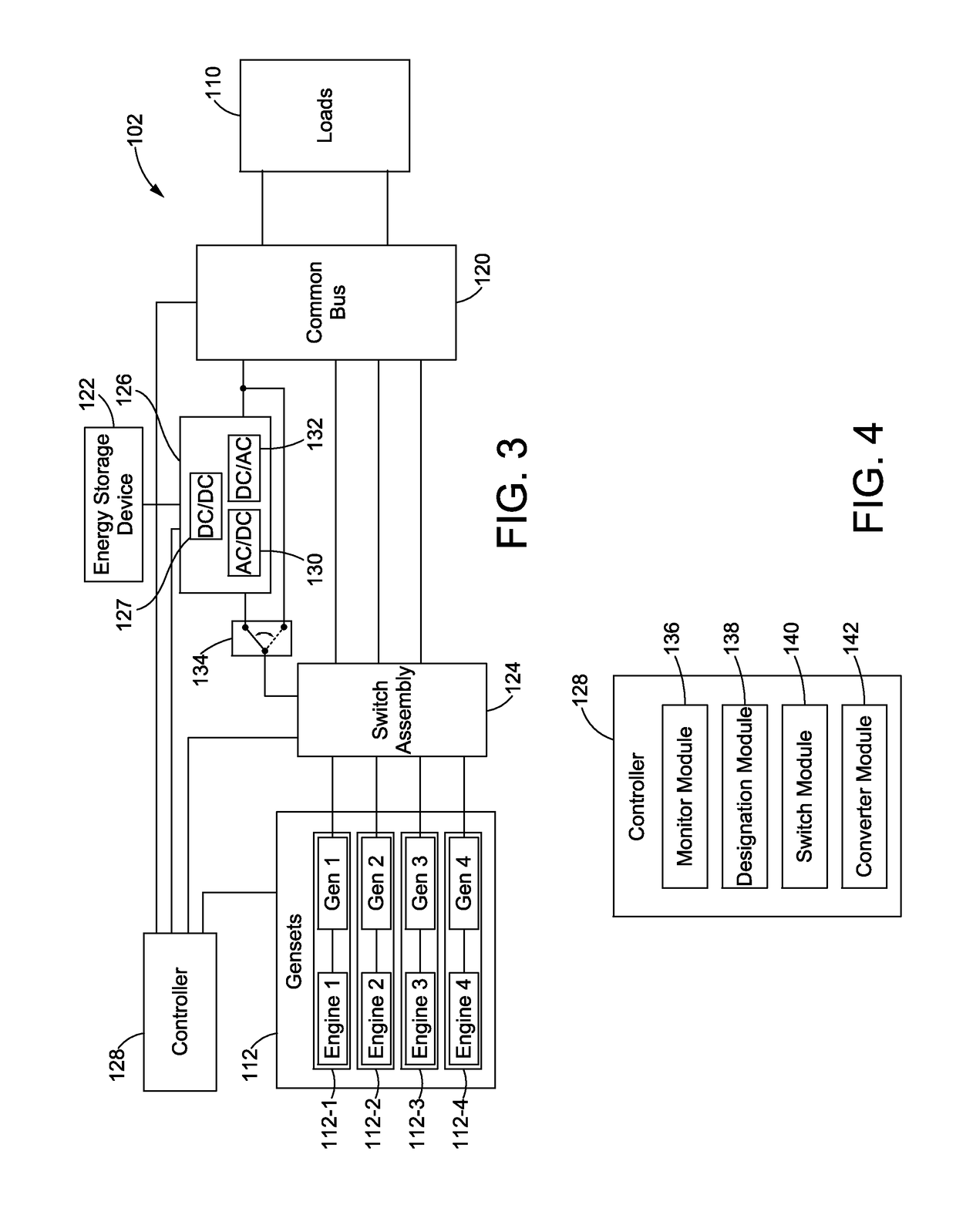
The present disclosure describes a variable speed genset system that includes multiple gensets, a switch assembly, a power electronics circuit, and a controller. The controller can designate some gensets as variable speed gensets and others as constant speed gensets. The switch assembly connects the variable speed gensets to the power electronics circuit, while the constant speed gensets are connected to the common bus. Optionally, an energy storage system can also be connected to the power electronics circuit to provide better performance and maintain uninterrupted operation. The technical effect of this disclosure is a more flexible and efficient system for generating power that can adapt to changing needs.

Problems solved by technology

While constant speed genset configurations are relatively simple and easily installed, operating each genset at constant speed is not economical in terms of fuel consumption.
Furthermore, apart from high noise levels, constant operation at high speeds leads to more wear and maintenance on the genset system.
In addition, constant speed genset configurations are prone to uneven loading between gensets with the above described art, which can in turn cause uneven and premature wear within the genset system, if not properly accounted for.
Moreover, it is not only costly to implement power electronics circuitry for each and every genset in the configuration, but it is also costly to maintain the various electronics involved.
Furthermore, the variable speed genset configurations, as with constant speed genset configurations with various load sharing schemes, are still prone to uneven load distribution, or uneven loading between gensets which can ultimately cause uneven and premature wear within the genset system and also lead to unplanned maintenance or failures.
The problem is even more compounded when only one or a subset of gensets are variable speed gensets while others are constant speed gensets.
This, however, negatively impacts operations and can be prone to error with significant failures and maintenance issues.
In addition, the configuration may allow for staggering maintenance schedules for gensets by appropriate loading over time.

Method used


Image

  • Flexible Variable Speed Genset System
  • Flexible Variable Speed Genset System
  • Flexible Variable Speed Genset System

Examples


Embodiment Construction

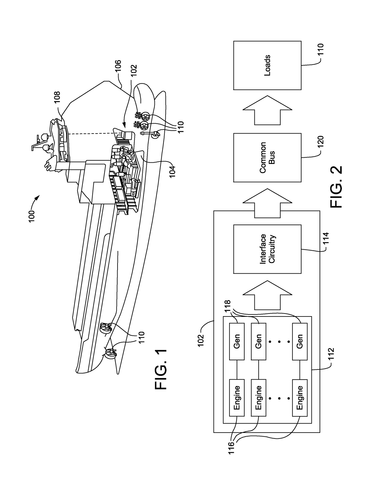
[0016]Referring to FIG. 1, one exemplary machine 100, such as a marine vessel, having a variable speed genset system 102 is provided. In the particular machine 100 shown in FIG. 1, for example, the variable speed genset system 102 may be anchored to a platform 104 within a hull 106 of the machine 100, and at least partially controlled from a bridge 108 or any other suitable location onboard and / or offboard the machine 100. Moreover, the variable speed genset system 102 may be used to supply power to one or more loads 110 of the machine 100. For example, the loads 110 may include any number of devices that consume mechanical and / or electrical power, such as motors for powering propellers or other drive mechanisms, lighting systems, heating, ventilation and air conditioning (HVAC) systems, water pumps, and any other primary or auxiliary load of the machine 100.

[0017]Although the machine 100 shown in FIG. 1 is depicted as a marine vessel, it will be understood that the machine 100 may ...


PUM


Abstract

A variable speed genset system is provided. The variable speed genset system may include a plurality of gensets, a switch assembly coupling one or more of the gensets to a common bus, a power electronics circuit selectively coupling the switch assembly to the common bus, and a controller in electrical communication with the gensets, the switch assembly and the power electronics circuit. The controller may be configured to designate any one or more of the gensets to operate as variable speed gensets and one or more of the remaining gensets to operate as constant speed gensets, engage the switch assembly to couple the variable speed genset to the power electronics circuit, and engage the switch assembly to couple the constant speed gensets to the common bus.

Description

TECHNICAL FIELD[0001]The present disclosure relates generally to genset configurations, and more particularly, to systems and methods for controlling variable speed and constant speed gensets.BACKGROUND[0002]Genset systems, or networks of engine and generator combination sets, can be used to produce power in a variety of different applications. In marine vessels, for instance, multiple gensets can be harnessed together to drive primary loads, such as propellers or other drive mechanisms, as well as various auxiliary loads, such as heating, ventilation and air conditioning (HVAC) systems, lighting systems, pumps, and the like. In particular, the engine in each genset can be mechanically coupled to the corresponding generator and any mechanically-driven loads, while the generator can be electrically coupled to electrically-driven loads. Different genset configurations may be available for different applications, and selecting the appropriate configuration includes consideration of fac...

Claims


Application Information

Patent Timeline
IPC IPC(8): H02J3/46H02K7/18G05B15/02
CPCH02J3/46G05B15/02H02K7/1815B64D2221/00H02J13/00007H02J2310/44H02J2310/42Y04S40/121Y02E60/00H02J3/466
Inventor REDDY, SURESH BADDAM
Owner CATERPILLAR INC
Learn More