Control circuit and method for a pwm voltage regulator

a voltage regulator and control circuit technology, applied in pulse techniques, dc-dc conversion, power conversion systems, etc., can solve the problems of increasing manufacturing costs, unable to meet a variety of applications, and only improving the transient response, so as to speed up the transient response, improve the transient response, and improve the flexibility of changing the capability.

Active Publication Date: 2012-12-06
RICHTEK TECH
View PDF44 Cites 18 Cited by
  • Summary
  • Abstract
  • Description
  • Claims
  • Application Information

AI Technical Summary

Benefits of technology

[0010]A control circuit and method according to the present invention achieve at least the following effects. First, there is no need of a threshold for load step detection because its triggering is only related to transient speed, and its response is directly proportional to transient speed and steps. S

Problems solved by technology

However, such an approach has two major problems.
First, the threshold of voltage variation is discrete, so transient response can only be improved when the droop-voltage at the output exceeds the threshold.
Second, the threshold of voltage variation is fixed, and thus it can't meet a variety of applications.
Additionally, in the event that the threshold setting relies on external components, additional pins will be required, which increases manufacturing costs and reduce the fl

Method used


Image

  • Control circuit and method for a pwm voltage regulator
  • Control circuit and method for a pwm voltage regulator
  • Control circuit and method for a pwm voltage regulator

Examples


Embodiment Construction

[0018]Traditionally, a PWM voltage regulator usually has an additional compensation circuit for filtering out the high-frequency component of a feedback signal. The present invention acts in a diametrically opposite way to provide a specially high-frequency feedback loop to control a high-frequency feedback signal for effectively improving a transient response of a PWM voltage regulator. The high-frequency feedback loop is a linear control loop and only acts on the high-frequency component of the control loop. The high-frequency feedback loop can be implemented by simple passive components and configurations.

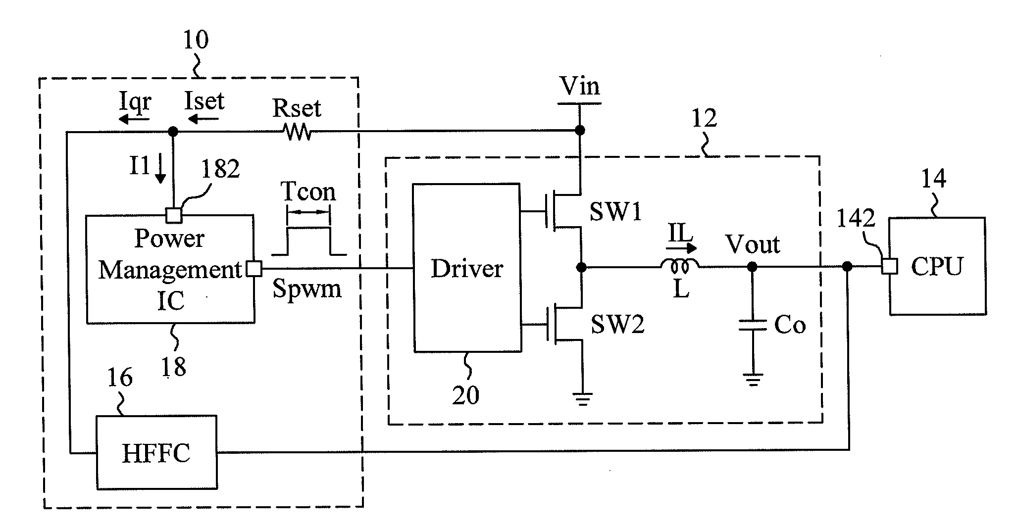
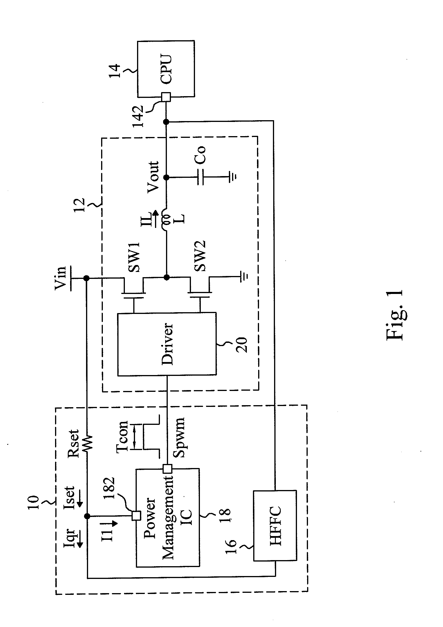
[0019]As shown in FIG. 1, an embodiment according to the present invention is applied to a constant current ripple (CCR) constant on time (COT) PWM voltage regulator using N-AVP control and having a PWM triggering mechanism similar to a valley current mode COT control loop. As is well known, the PWM voltage regulator includes a control circuit 10 and an output stage 12, and the ...


PUM


Abstract

A control circuit and method for a PWM voltage regulator combine a high frequency feedback technique with a constant on-time or constant off-time topology to improve the transient performance of the PWM voltage regulator. The PWM voltage regulator generates a constant on-time or constant off-time depending on a current for generating a PWM signal, and dynamically adjusts the current according to the droop-voltage at its output during a transient period. Therefore, the PWM voltage regulator boosts its transient response without any threshold for load step detection.

Description

FIELD OF THE INVENTION[0001]The present invention is related generally to a pulse width modulation (PWM) voltage regulator and, more particularly, to a control circuit and method for a PWM voltage regulator.BACKGROUND OF THE INVENTION[0002]Recently, central processing units (CPUs) have to bear highly dynamic load currents that usually change very quickly from a light load to a maximal-load. The CPU current transient may happen within 1 μs, smaller than a switching cycle of a typical PWM voltage regulator, whether it is controlled in a voltage mode or a current mode. For solving this problem, a PWM voltage regulator that serves to provide a voltage to a CPU is usually set with a threshold of output voltage variation so that when the variation of its output reaches the threshold, another non-closed loop adjusting mechanism can be triggered. For example, another PWM on-time can be triggered or its off-time can be immediately stopped or the duty of a PWM signal can be increased. However...

Claims


Application Information

Patent Timeline
IPC IPC(8): H03K7/08
CPCH02M2003/1566H02M3/156H02M3/1566
Inventor WAN, YI-CHENGHUANG, JIAN-RONGCHEN, WEN-WEI
Owner RICHTEK TECH
Why Eureka
Try Eureka