Optical current sensor based on Faraday magneto-optic effect and current measurement method thereof

A Faraday magneto-optical and current sensor technology, applied in the direction of measuring current/voltage, measuring device, measuring electrical variables, etc., can solve the problems of difficult to adapt to the power system, complex insulation structure, magnetic hysteresis, etc., to achieve insulation performance without affecting , The effect of good transient performance and large range

Inactive Publication Date: 2018-01-30
CHONGQING UNIV
View PDF6 Cites 17 Cited by
  • Summary
  • Abstract
  • Description
  • Claims
  • Application Information

AI Technical Summary

Problems solved by technology

Traditional electromagnetic current sensors have many disadvantages, such as: complex insulation structure, large volume, easy to generate magnetic saturation ferromagnetic resonance, and hysteresis, etc. It is becoming more and more difficult to adapt to the needs of power system development
Although the traditional electromagnetic current sensor is also constantly improving, it cannot fundamentally change its shortcomings.

Method used


Image

  • Optical current sensor based on Faraday magneto-optic effect and current measurement method thereof
  • Optical current sensor based on Faraday magneto-optic effect and current measurement method thereof
  • Optical current sensor based on Faraday magneto-optic effect and current measurement method thereof

Examples


Embodiment 1

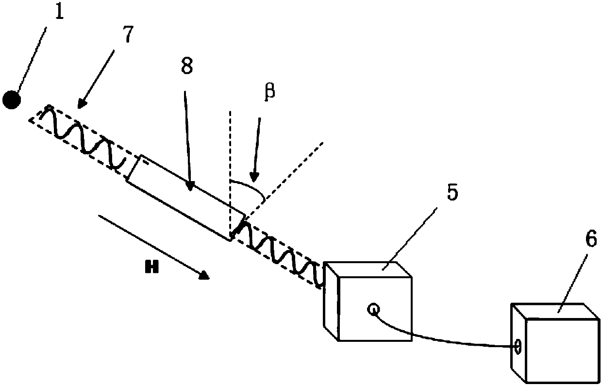
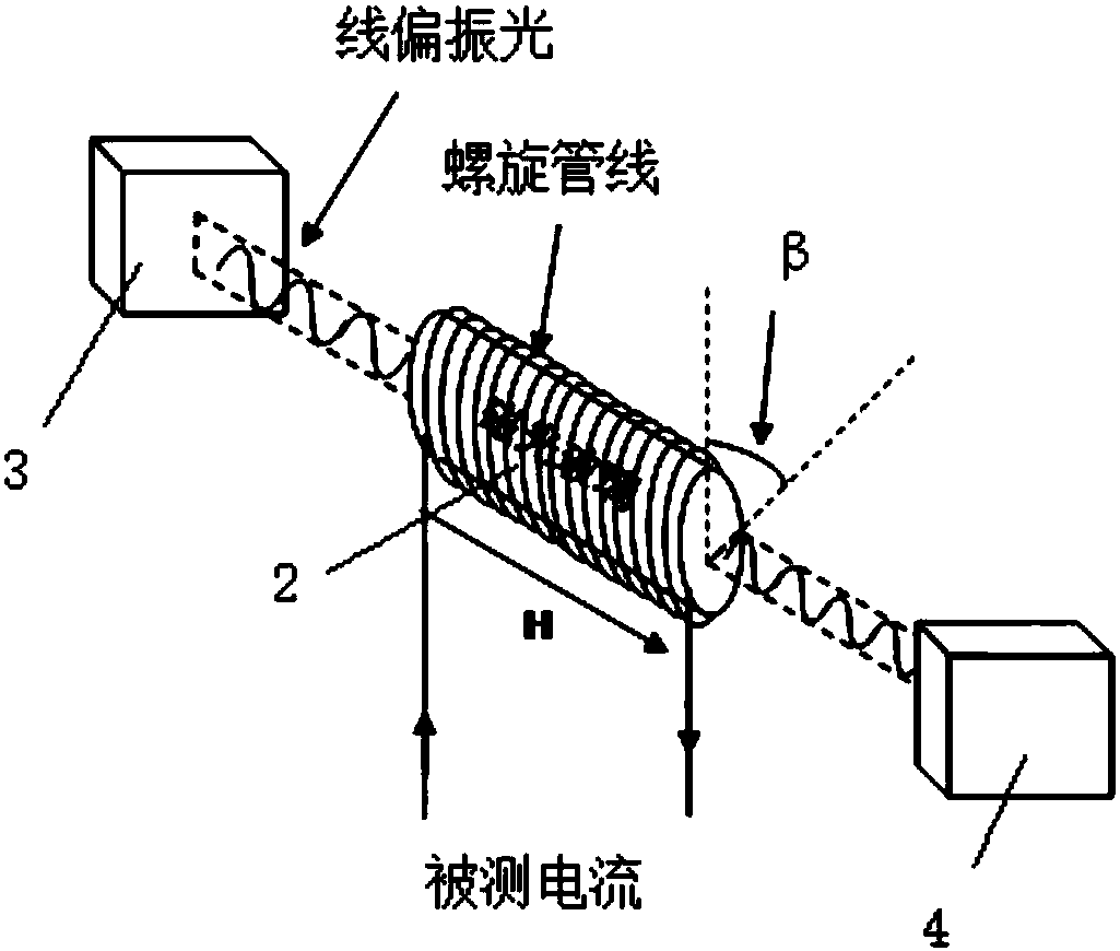
[0046] Such as figure 1 and figure 2 Shown is a schematic structural diagram of Embodiment 1 of the optical current sensor based on the Faraday magneto-optical effect of the present invention. This embodiment is based on the optical current sensor of the Faraday magneto-optical effect, including:

[0047] The laser generator 1 is used to generate polarized laser light with a predetermined wavelength. The laser generator 1 in this embodiment generates polarized laser light with a wavelength of 632.8nm. At this wavelength, the Verdet constant of the selected magneto-optical glass is the largest;

[0048] The integrated probe 8 includes a magneto-optical medium 2, and the two ends of the magneto-optical medium 2 are respectively provided with a polarizer 3 and an analyzer 4, and the polarizer 3 and the analyzer 4 are respectively insulated and packaged at both ends of the magneto-optical medium 2 ; In addition, the integrated probe also includes a fixed bracket and packaging, ...

Embodiment 2

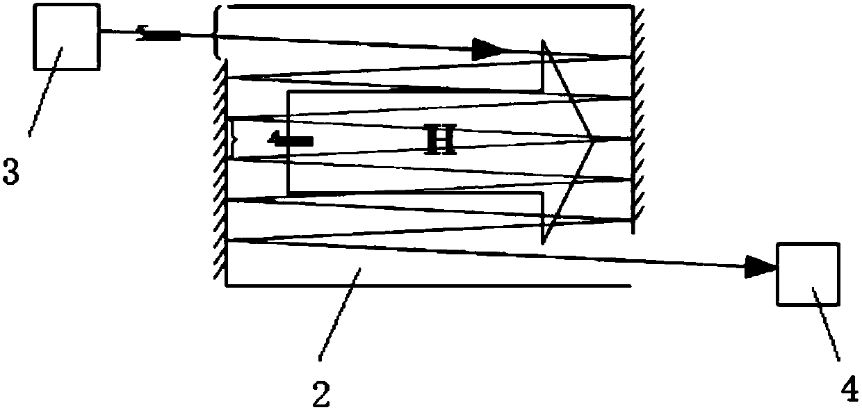
[0067] Such as image 3 As shown, it is a structural schematic diagram of the integrated probe of Embodiment 2 of the optical current sensor based on the Faraday magneto-optic effect of the present invention. This embodiment is based on the optical current sensor of the Faraday magneto-optical effect, including:

[0068] The laser generator 1 is used to generate polarized laser light with a predetermined wavelength. The laser generator 1 in this embodiment generates polarized laser light with a wavelength of 632.8nm. At this wavelength, the Verdet constant of the selected magneto-optical glass is the largest;

[0069] The integrated probe includes a magneto-optical medium 2, and the two ends of the magneto-optical medium 2 are respectively provided with a polarizer 3 and an analyzer 4, and the polarizer 3 and the analyzer 4 are respectively insulated and packaged at both ends of the magneto-optical medium 2; In addition, the integrated probe also includes a fixed bracket and ...


PUM


Abstract

The invention discloses an optical current sensor based on the Faraday magneto-optic effect. The optical current sensor comprises a laser generator which is used to generate polarized laser of a set wavelength, an integrated probe which comprises a magneto-optical medium, a photodetector which is used to convert an optical signal into an electrical signal, and a data analyzing and processing device which filters out noise through the combination of hardware filtering and software filtering to acquire a good response effect. A polarizer and an analyzer are arranged on two ends of the magneto-optical medium respectively, and are insulatedly packaged on both ends of the magneto-optical medium respectively. The laser generator and the polarizer are connected through an optical fiber path, andthe photodetector and the analyzer are connected through an optical fiber path. The invention further discloses a current measurement method of the optical current sensor based on the Faraday magneto-optic effect.

Description

technical field [0001] The invention belongs to the technical field of non-contact optical current sensor measurement, in particular to an optical current sensor based on the Faraday magneto-optic effect and a current measurement method thereof. Background technique [0002] With the development of the power system, the system has higher and higher requirements for safety and stability. As an important device for energy measurement and relay protection in the power system, the current sensor's accuracy and reliability are closely related to the safe, reliable and economical operation of the power system. Traditional electromagnetic current sensors have many disadvantages, such as: complex insulation structure, large volume, easy to generate magnetic saturation ferromagnetic resonance, and hysteresis, etc. It is increasingly difficult to adapt to the needs of power system development. Although the traditional electromagnetic current sensor is also being continuously improved...

Claims


Application Information

Patent Timeline
Patent Type & Authority Applications(China)
IPC IPC(8): G01R19/00
Inventor 杨鸣司马文霞孙魄韬袁涛郑荣锋张涵
Owner CHONGQING UNIV
Why Eureka
Try Eureka